Sunday, November 29, 2020

Python Hardware Sequencer Part I: PNG to CV Converter

Let's see what we can do with single board computers (SBC) and DiWhy audio. It's of course a very broad topic.  

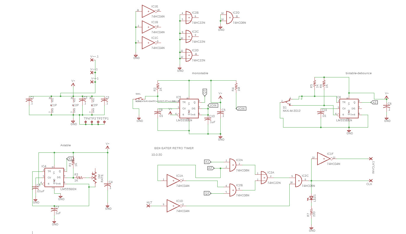
This time I begin building a modular synthesizer sequencer/control voltage logger based on a Raspberry PI running Python.

I already experimented with Python and SBCs to create simple blinkenlites using PyGame--post is here.  

Recently I created another SBC python program that turns a PNG image into a series of Y-values along an X axis. From here, it'll should easy to turn these Y values into CVs using a I2C D to A converter, with each Y value buffered then going to the sequencer's output, when a trigger or clock is received on a GPIO pin.
 
PNG PONG? I got the "PNG to Y-values" part of the project working this week, doing some of the coding while on vacation; meanwhile, my psychiatrist girlfriend seemed to enjoy the peace and quiet. 

Python is still a bit new to me, I am embarrassed to say that for my day job I am still involved in the good old LAMP stack and perl but like all good things it's time to move on. 

And as any Python programmer could will tell you: as an interpreted language (how it works is more complex than  thought--read the post here) Python is not always fast but can do damn near anything.  And is really easy and forgiving language. 

For the code below I used numpy, a data science tool for manipulating data arrays, as well as Matplotlib, a popular Python module used to create graphs, as well as Pillow ("PIL"), used for graphics manipulation. These modules are green like a mountain and tall like a tree; with some coding skill under your belt, you can log, image, map and do damn near do anything.
 
Here are the design goals for this part of the sequencer so far:
  • Read a PNG file for data input (I am not sure there is another sequencer that does this?). 
  • Convert the PNG file to a B&W image
  • Turn the resulting data into a numpy structure.
  • Flip the array its side (270 degrees).
  • Y becomes (ultimately) a CV output.
This gets me into a new programming world. I didn't know Python could extract and manipulate numeric data from an image file, but indeed it can--in many ways--read more here

As far as the code below, this is the first thing I've ever written using matlab, PIL and numpy so I figure there are many ways to improve it.....for instance, the rotation/"flip" step isn't necessary; the code could have read each column's values of the numpy array and returned the first Y value "hit", then break, but I want to be able to flip the logged PNG by 180 degrees so might as well flip it 270 before extracting the Y values. 

Nevertheless I will probably end up writing another version of the code below using the [a:b:c,x:y:z] method of extracting columnar numpy data and see which script performs better--the latter might have less lines of code? but for now what I have works. UPDATE: Done, see bottom of post. The version without Numpy array "flips" runs much faster.

OK after the numeric extraction is done:
  • Create a python list of the Y-data along w/ the Numpy data.
  • (To do down the road: Create a bar graph of the output using the amazing matplotlib, which could perhaps be displayed on the sequencer's OLED.)
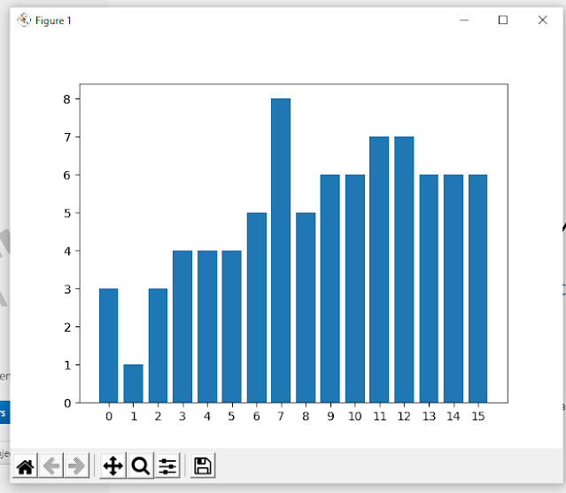
For testing I used a 16 x 10 PNG file as source. The code (below) vs. this tiny file took a few seconds to run, so I figure 4K x 2K PNGs probably won't cut it, since it will take too long to run and generate more data then is needed, but a 128 x 50 pixel PNG might. 

The test graphic for my code:


..........that simple PNG file returns this bar graph (as well as a Python list and numpy data structure), which appears to be correct, based on the PNG input:


Here's the Python 3 code so far for PNG image to data conversion; first with the nifty numpy rot() methods to flip the image, then, below that, "straight up" numpy:

##########################

import matplotlib.pylab as plt
import numpy as np
from PIL import Image

###########  file locations ##############
file_loc = "./PNG2cv/tiny.png"
bw_file_loc = "./PNG2cv/tempbw.png"

#use PIL to create BW image, resave BW to HD
image_file = Image.open(file_loc) # open colour image
image_file = image_file.convert('1') # convert image to black and white
image_file.save(bw_file_loc)

#imread method is matplotlib--open graphics file >  output is numpy array
#turn it to Numpy array
im = plt.imread(bw_file_loc)

#get row and column count
output_y = []
output = []

#for this to work at all, you have to rotate the array.
im4 = np.rot90(im,3) #rotate 270 degrees  "3 is 3x90"
x1 = im4.shape


rows = (x1[0]) #number of rows
columns = (x1[1]) #number of columns
 
c = 0

r = range(columns)

for a in im4:
 
    y = 0
    for x in r:
       
       if (a[x]  < .1):            
           output.append([y])
       y = y + 1
    c = c+1

 
out5 = np.asarray(output)
list1 = out5.tolist()  #turn into python list 


strip_list = []
for tt in list1:
    xp = tt[0]
    strip_list.append(xp)

print(strip_list) #print values extracted as Python list

#bar graph require X values, matching # of items in data set, as array of string values 
#(not int--strings!).

x_axis = []

for q8 in range(rows):
    x_axis.append(str(q8))
#print (x_axis)
#show bar graph of y values

#show this as a bar graph.  This is optional.
plt.bar(x_axis,strip_list)
plt.show()

#########################

UPDATE: I am just getting started with coding this, and have posted the py files and test PNG files here.  get-photo7b.py captures the bulk of the code to date. 

UPDATE.  Here is the code again without the flipped numpy arrays. Rotating an array 90 * x degrees is a cool feature but does it make the program run too slow?  Not sure how this will end up going, but, without flip the code runs about 4x faster so flips might not make it to final build.

Update: 12-10-20 with 3K x 1000 pixel PNG files the code below still runs pretty quickly. Not so much for the code above. We might have a winner for the PNG to array conversion part of this:  
##########################

import matplotlib.pylab as plt
import numpy as np
from PIL import Image

###########  file locations ##############
file_loc = "./PNG2cv/tiny.png"
bw_file_loc = "./PNG2cv/tempbw.png"
 
image_file = Image.open(file_loc) # open colour image
image_file = image_file.convert('1') # convert image to black and white
image_file.save(bw_file_loc)
 
im = plt.imread(bw_file_loc)
x1 = im.shape
 
rows = (x1[0]) #number of rows
columns = (x1[1]) #number of columns


r = range(columns)
for p in r:
    c = 0
    for a in im[:,p]:

        if (a < .1):
            c = rows - c - 1
            output.append(c)
            break

        c = c + 1

#list below is output values we want.
print(output)
#print(out5)


#create numpy array w/ output values
out5 = np.asarray(output)
x_axis = []

for q8 in range(columns):
    x_axis.append(str(q8))
print (x_axis)
#show bar graph of y values
plt.bar(x_axis,out5)
plt.show()

#####################

Down the road, lots more to do:
  • Flip the output array to x degrees (to say flip the sequencer's output values, something I always want to be able to do with a traditional sequencer--and easy with python/numpy right?)
  • Reduce size of PNG to say 200 x something before processing? Not sure, and not sure if Python can do that, but I figure it probably can--Photoshop can anyway.
  • Capture 16x pot analog values to a numpy data structure (and create a PNG image in the process?) and then use that to control the sequencer's output values. Adding or otherwise manipulating data in a numpy structure is easy (good vids for that are here and here) so why not?  The pots could augment/change  the PNG logged data and/or be used for 16 values at input in the mod synth sequencer traditional manner. Still thinking about this.
  • Save some of the data set (perhaps all Y values?) into a sqllite DB. That way manners of sequencer data can be easily stored and retrieved....I can see sqllite being really useful for a ton of stuff we do in the audioDIY world.  
  • Upload PNGs to the SBC using the web--so make the sequencer an "IOT" device--you can load new data into the sequencer without having to touch its front panel.
I can think of lots of other features....this will be fun.

PNGLEBERRIES? That's it for now.  More to come with this project in upcoming posts.

UPDATE 12-4-20: After doing manditory "windows updates" to Windows 10 v2004, for me, Python/Numpy stopped working.  Check out the info here.  To fix: open terminal and enter this:  pip uninstall numpy    then reinstall older numpy:pip install numpy==1.19.3 

UPDATE 12-10-20 here are some new functions for the project, that manipulate numpy arrays in ways that should be useful to sequencing....

#############################
def reduce_np_numbers(nparray,y):
    #reduces number of items in an np array to y
    # still doesn't always work for larger values of y
    # comes out w/ array 1 element too large, fix this.
    if nparray.size <= y:
        return nparray
    else:
        x = int(nparray.size / y)
        reducednp = nparray[0:-1:x]
        
        return reducednp


def list_to_np(list):
    #create numpy array w/ output values
    out5 = np.asarray(list)
    return out5

def add_to_array_y(nparray, x):
    #add or subtract values from np array.
    p = nparray + x
    return p

def mult_array(nparray, x):
    #multiply each array value by x
    if x == 0:
        x = 1
    p = nparray * x
    return p

def clip(nparray, min=0, max=1023):
    #set min and max values for everything in array
    x = nparray.clip(min, max)
    return x

def scale(nparray,scalevalue):
    #scales all values in array to y average. scalevalue is a percent. Output rounded to int.
    scalevaluex = scalevalue * .01
    print(scalevaluex)
    q = np.average(nparray)
    print(q)
    condlist = [nparray<q, nparray>q]
    up = 1 + scalevaluex
    down = 1 - scalevaluex
    choicelist = [nparray*up, nparray*down]
    a1 = np.select(condlist,choicelist,q)
    a2 = np.rint(a1)
    return a2

Friday, November 13, 2020

Retro Computer Audio--6502, Timers, Emulators, and Assembler Madness

Hello again! From a few posts ago, I had an idea to build an Arduino knockoff using an RCA1802. But another tech was already doing it (here), and his work is 1000x's better than mine will ever be, even if I worked on it for years. He even picked a better name for the project. Damn! 

However, my desire to learn more about computers at a deep level continues on many fronts: Von Neuman architecture, assembler, homebrew PC construction, blinkenlights, and yaddah.  

So where to start?  How about a timer? Why/why not? No matter what hardware I'll use for this adventure, I figure I'll need a timer that can step through CPU machine cycles and see if my code is working. Marvey let's build that.


To this end I found a great series of vids on youtube from Ben Eater where he fabs a simple 6502 PC (that's CPU used in old Apples and other early PCs) using breadboards--his "getting started" webpage is here. This is a complex subject, but the author explains things so clearly and patiently that even a tinitous distressed, OCD burdened, over the hill rock and roll guy like me can follow along. 

In addition to 6502 madness, the vid series has a very good series of explanations about how the venerable 555 timer works--part I is here. Mr. Eater uses 3x 555's in a monostable/bistable/astable timing board for his own 6502 machine language "Hello World" project. 

Let's motorize this pursuit! I laid the Eater timer out in Eagle--as I've said many times, I can't breadboard to save my life and slapping together a gerber/getting it fabbed/getting it built is affordable and in the long run, seems more expedient. 

For this timer board--didn't work the first time, I made a few dumb mistakes, but 2nd go at it, the PCB works 100% as far as I can tell; he's the schematic:


And the board....


A couple of useless build photos:


It works. I have a gerber for this....if you want it, ready to send off to your favorite fab shop,  comment below, we will figure something out. Important! if you build this board make sure to tie HALT to ground to allow the circuit to work reliably, or wire in a switch between 5V (off) and Ground (run) to HALT. For my build I ran a 22 gauge jumper from GND to halt which is not shown in the photos above.

OK now what?  I bought a kit for the basic Eater 6502 hardware kit (here, scroll down the page) and this PCB for it (here, there are others) but while I'm waiting I figure I can get my feet wet with a 6502 emulator. There are lots online but I really liked the one here; it's simple--download the js and html stuff, stick the files on your PC, open with Chrome, and you're off.

Using that, with help from some vids, I created my first assembly language program--for me, the first one ever. Who needs hardware?   

OK the code below paints the background of the emulator's screen in whatever (limited) color you choose. 

Assembly language in general is unlike anything I've coded with before, but with assembler we're baking things down a very simple form, and as a reductionist, that's A-OK by me. Once I got the hang of this what you see below wasn't that hard tp figure out, and I figure assembly for relatively simple processors like this, for certain things, might be easier than C?  No mallocs, crazy pointers, C++ objects etc. anyway. Just goofy 3 letter codes, right?

So here is the code:

;LDY #$00 ; load offset Y 1 NOT NEEDED already 00?
LDX #$02 ; load h02 into X
STX $11  ; put X into special RAM MSB
LDY #$00 ; load offset Y 0
LDX #$02 ; load h02 into X
STX $11  ; put X into special RAM MSB
LDX #$00 ; load h00 into X
STX $10  ; put X into special RAM LSB
LDA #02  ; color of pixel to draw
STA ($10),Y  ; indirect memory addressing 0x0200 to get to 16 bits…..
JSR draw1

LDX #$03 ; load h03 into X
STX $11  ; put X into special RAM MSB
LDX #$00
JSR draw1

LDX #$04 ; load h04 into X
STX $11  ; put X into special RAM MSB
LDX #$00
JSR draw1

LDX #$05 ; load h05 into X
STX $11  ; put X into special RAM MSB
LDX #$00
JSR draw1

draw1:
INX     ; increase X register by one
STX $10 ; put that into RAM LSB
STA ($10),Y  ; store A register (color) to screen
CPX #$00     ; compare, is X at h00?
BNE draw1
RTS

I am not sure the code above is as optimal as it could be but it works.

Going forward: Next up is build the Eater homebrew 6502. To further flesh this out I have some ancient Analog devices parallel A to D's, it would be interesting to see if I can get those going with the home brew 6502 circuit.  

OK which begs the question: Why can't I just use an Arduino to learn how computers work at their deepest level?  Anything I can do on a 6502 can be done on a modern CPU, right? But the 6502 makes me feel as I am starting out simple. And best of all: For me, it's like, well, you know: all new, no matter what.

OK that's it, until next time don't breathe the fumes.

Saturday, November 7, 2020

In the End, Windows Gets us All: Siglent, SigRok, VISA, and a Weekend of Lab Double Happiness

Sometimes you gotta solder and sometimes you gotta spend? I have been using junk laptops at my bench for years, castoffs with broken trackpads, slow CPUs, dim screens ready to bite the big one. Some of them run Linux, some of them MacOS, occasionally Windows. 

Too much crap, it had to stop. 

New NUC Windows 10 System

NUC ME UP SCOTTY!

Sooo.....I got out the credit card and bought an Intel NUC10I7FNH running Windows 10 Pro. Yes, Windows. Yes, Microsoft. I guess this day had to come. Too many software packages I wanted to run seem to work best with Windows, and perhaps Windows OS gets us all in the end.  

Intel based desktop PCs may one day be a thing of the past, but for now, the NUC abides; it's tiny, bench friendly, and packs a wicked punch in a small footprint. Doesn't take up much space on the bench. 

OK, it was a fair amount of money. I'll deal with that later.

First thing I want to do with this new PC:

LOGIC ANALYSIS

Sigrok and Roll:  If you haven't heard of Sigrok, run, don't walk, and get it here. It's open Source/free software that gets you (among many other things) an electronics logic analyzer at super low cost.  

You can buy a super cheap USB Saleae clone (neighbor and fellow audio geek mvcl gave me a $5-$10ish 24Hhz/8 probe he had sitting around as a gift--thanks dude). 

Pulseview  is the logic analysis GUI tool that comes with Sigrok. If you work with digital electronics, a decent logic analyzer is essential. Pulseview is fantastic and is FREE.

Something like 130 different protocols are decoded (here) which includes "stack decoders"--what your data means without having to constantly look at the IC's datasheet; I/O formats (here); DMM UI is here. CLI is here

Since Sigrok is open source you can learn how things work by studying its code. This sort of thing restores my faith in humanity.  Recommended viewing: an extremely informative video and tutorial, from one of the guys who wrote Pulseview, is here

"Windows Wins": I couldn't get the Pulseview or CLI Mac DMGs to install on my Macbook Pro; then I spent an entire evening trying to compile Sigrok from source on Fedora 29 before giving up and installing the it via yum . But, the yum build of Sigrok for Fedora 29 kept crashing, so, I installed it on Windows.  

It works, but you have to manually install drivers for the Salae clone frequently.  Read on.....

MVCL's gifted $10 Saleae Clone. Note the broken grabber. Yeh, I did that.

Here are steps to get the Saleae clone working with Windows 10:

  • Run Zadig for pulseview/Windows; list all devices (Zadig comes with Pulseview)
  • In the Zadig app, find the fx2lafw device from the drop down
  • If necessary change the driver for fx2lafw to "WinUSB"
  • Note: Inside the Zadig app, even when the driver is listed as "WinUSB", I have seen the saelae clone frequently not recognized by Windows until I click the Reinstall Driver button. So--reinstall what appears to already be installed....
  • Careful!  Don't change drivers for any other devices....


With the correct driver in place:
  • Open Pulseview/Windows
  • Click on the down arrow at the top+center of the pulseview window > connect device
  • Choose driver "fx2lafw"
  • Click "scan for devices using the driver above"
  • Choose the Saleae clone
  • You are ready to scan!
Update 7-3-2022.  I am using logic analyzers more and more as I am further dragged into the world of Embedded C. "Windows loses": I got fed up with having to fix broken Windows drivers on the Windows using Zadig. I installed Pulseview on a Raspberry Pi 4 using the instructions here (read the comments as well, which mention a critical fix to one of the many apt install commands:  sudo apt install libevent-dev). To my amazement Sigrok and Pulseview compiled on RPi4 without issue....Pulseview on RPi  works better since the fx2lafw Linux driver recognizes the Saleae clone every time....I RDP to the Raspberry Pi from windows, then run Pulseview from that.

Update: Sorry to admit: Got out the credit card again, and again I spent a huge butt ton of money of a real Salae logic analyzer, not a $10 clone. Nothing wrong with Pulseview--it's wonderful software--and was a great starting point for learning about logic analysis--but the Salae clone hardware, Windows driver issues, and flimsy probes were driving me nuts.

CAD:

Next up: Eagle and Fusion 360. This is for PCB layout and 3D design. I have argued about Eagle vs. Kicad at length with my maker friends; they tell me anyone who doesn't use Kicad should be shot. But as a long time paid subscriber to Eagle, the folks at Autodesk threw in a licensed copy of Fusion 360 "for free" to keep me in their world. It worked; I have no complaints about any of it, except, Eagle is an odd program, but an odd program I sort of know. There must be a girlfriend analogy in there somewhere? 

"Windows Wins": I have always used Eagle on Windows, pretty much. I have it on Mac which I never use. For what I do, it's good enough.  Update: 10-11-23 Autodesk is discontinuing Eagle. I have moved on to Kicad. See the post here.

Next up: 3D printing. Been there, done that, post is here. Yes, it all works on Windows. Let's move on.

DEVELOPMENT:

I installed PyCharm Python IDE and Microsoft Visual Studio Community for C/C++  programming.  

Amazing that there are personal versions of these excellent programs, compiled for Windows for $0.  "The Cherno" has great Youtube videos covering Visual Studio Community on Windows, here

And: for AVR development: Atmel Studio 7 for Windows, get that here. Good low key videos about basic set up and use for Atmel Studio are here

For compiling C++, outside of Visual Studio, I installed minGW, mostly to debug C functions for embedded systems without having to flash an MPU over and over.  After getting that going however, I discovered a C compiler "cl" (compile/link?) that can be run from the Visual Studio terminal, info here.  Works great!

I also installed VSCODE--excellent free software from Microsoft--which I have been using for RP2040 development (wait--excellent free software from Microsoft?  In one sentence? Bill Gates has retired?

For when I am not using the amazing Online GDB website here for C and C++ experiments and rapid development, I also installed CodeBlocks  for Windows--awesomely powerful and free.   

Linux On MS Windows?

Cats, sleeping with dogs? Turns out Windows has surprisingly good and easy to install Linux virtualized hosts you get for free (well, after you buy W10, right?).  

It's called "Windows Subsystem for Linux" or WSL.  

Current version as of the writing of this blog post is WSL2. Check out WSL2 here. I got that along with the Fedora WSL build (here) since I mostly work with Redhat/Centos/Fedora Linux, but Ubuntu is available for free here as well as Debian, SUSE and a few others. 

To get at Windows data from the the Linux VM open the WSL2 Linux system and cd to /mnt/c/[windows_foldername], cool! 

"Windows Wins (or does it)?  WSL2 is command line only. Damn. I want to be able to run gnome and so on.  Can we find a way to get this going?  You'd need to be able to run X11 on the WSL2 host.....we need an Xwindows server on WSL2. 

Um, no.  Doesn't work.  I installed a Ubuntu WSL2 VM, but then I burned up at least 5 hours trying to get x-windows processes of any stripe running. To make a long story short--DOH!--the problem: WSL2 can't run systemd and you need that for X11!!

But, I did find a way to get a GUI working on WSL2 Ubuntu, see video here. Another post about the same thing is here

Both solutions use Windows RDP protocol to get at the Ubuntu GUI, and thus doesn't need a WSL2 X11 server.  

Update 3-10-21 this is described in the videos above but I often find myself forgetting: if you follow the instructions to set up an xrdp GUI on Ubuntu, you need to start the xrdp daemon each time or else RDP session will fail.  

Command to do that:

sudo /etc/init.d/xrdp start

Another way to generate a GUI from WSL2 would be to run Xwindows on Windows and then use DISPLAY exports from the WSL2 VM....I'll figure out that another day.

Update 5-16-21 OK this method works as well. X11 windows on Windows!! Indeed--cats sleeping with dogs. 

Use VcxSrv. 

Get VcxSrv here. Amazing--works great!  I had no idea. 

Good video about this is here

To get it going, run xcxsrv on windows, then go to the Ubuntu WSL2 VM and the issues these commands:

DISPLAY=[windows10 IPV4address]:0  (example: DISPLAY=192.168.1.22:0)

export DISPLAY

Then to test we can run something like xclock:

xclock

Another tool for Linux folks on Windows is cygwin, which allows users to run familiar Linux commands right from the Windows terminal (tools like grep).  

I downloaded and did a default install.  You have to update environment PATH for the cygwin commands to be found by the OS, info about how to do that is here. I think every windows machine needs cygwin.

UPDATE, 3-19-22: I read that Windows 11 natively supports their own version of X Windows for WSK2 (so no need to run XRDP ) but I haven't tried it yet--read more here

UPDATE 4-2-22: After a lot of time spent with WSL2, I ended up purchasing and installing VMware Workstation Pro, at USD $199 it's not freeware, but what's my time worth? I installed VMware WS on the NUC, then installed an  Ubuntu 20.10  virtual machine inside that. 

Seems to work, as does hijacking the host's USB communications for things like PROM programmers, MCU/dev board firmware programmers, and so on--the things a maker needs a Linux system for--so for example I can program an Arduino from Windows or the Linux VM.

UPDATE, 9-10-22: an interesting alternative to XRDP, WSL2, and VsxSrv, for running Linux Xwindows apps on MS Windows, is MobaXterm. Powerful app and free for home use. Very easy to use: you install it on Windows, create an SSH session, choose the IP of the target Linux system running X11, type in the user you want to use and go. 

For my Ubuntu VM I had to do literally zero setup after running the Windows installer for Mobaxterm. 

I've had MobaXterm on the the bench for a few weeks and so far has worked flawlessly--using MobaXterm any X app for Linux I run on the Ubuntu virtual machine or Rasperry Pi has run seamlessly on the bench Windows NUC. Once again, it's FREE. Amazing.    

UPDATE 10-8-23  I continue to love MobaXterm--amazing free program to run x11 apps on windows--but for Linux Mint Cinnamon 21 I had to to install a few additional Linux services so MobaXterm would work:

install openssh: sudo apt-get install openssh-server -y 

turn on remote X11: in /etc/lightdm/lightdm.conf.d create a file called 100-custom.conf with this content: [Seat Defaults] xserver-allow-tcp=true 

make sure port 6000 is listening (google that if you don't know how, I allowed x11 through ufw) 

after that I could create an SSH session to the laptop running Mint and (to test) type xclock at the Xmobaterm prompt.  I see the x11 clock on my windows PC--it works.

VERSION CONTROL: GIT AND GITHUB

Someone has to say it: You can't do any sort of efficient code work without version control.  Especially if you have machines all over as I do: work, home, laptops, etc.--and expect any sort of efficiency hopping from system to system.

The leader right now is git (here) and github (here).  Windows git is very similar to Linux, except for the damn carriage returns. I won't go into detail about how to install and use git and github, maybe that's for a future post, but, there is already an absolute ton online to get you started. 

But!!! if you don't know the basics of using Git and github, run, don't walk, download and install them, then take a few hours to learn their basics (good basics tutorial is here).

Yes you heard that from audiodiwhy and everywhere else: Once you are managing your code and project files using git I think you will wonder how you ever survived without them.

Once installed, you can run oh-my-posh for Windows to beautify the github cursors.  This means installing Windows Terminal (here), oh my posh (here), getting a font for Windows Terminal (Meslo nerd font--here) and then invoking it by altering the settings json file (use PowerShell within Terminal--which works--here).

BENCH AUTOMATION

I went down yet another rabbit hole because the bench tool automation provided by Sigrok doesn't support most of my Siglent bench devices. 

Yep--Siglent. I know there is discussion about Siglent's poor security measures, politics surrounding this stuff, etc., but I can't afford top shelf bench gear, and based on my own limited EE skills (read my posts, is it obvious?) it'd be pearls before swine if I bought a gazillion dollar Keysight scope. Yep, for many of us, Siglent is affordable and works!

Sigrok led me to online discussions of controlling all my Siglent bench gear with Python, which led me to National Instruments NI-VISA. That way all my lab bench gear can be controlled from the new W10 system and a Python front end I can program any way I want. 

PUT IT ON YOUR NI-VISA:

What is VISA? Like MIDI, a bunch of manufacturers got together and came up with the a protocol for that would work across their different wares. 

For those with way too much time--the Wikipedia for VISA is only a few paragraphs--read more about the history of the VISA protocol here

Great that manufacturers agreed on the VISA protocol, but what do we use to send information from a PC to a VISA compliant piece of test gear?

We can send read-only and "change a setting" sort of statements to our VISA bench gear using a protocol called SCPI (I have heard this called "skippy").

Fine: how to get SCPI going? 

Download free Windows (Windows only!) software from National (here). 

Install all of that. 

Next, hook a USB cable between your computer and your lab gear. Ethernet works as well, assuming your bench device supports it.  

The other SCPI??


An aside: I work with IP networking all the time, so I tried to get ethernet going with my new NUC and  my various Siglent bench dookies that had an RJ45 jack; all worked well with static IPV4; all except my 3303 Siglent power supply

IPv4 seemed buggy on that device--at the very least, the static IP settings seemed to get wiped each time I power cycled, but it was way more bizarre than that. I called up Siglent support, not expecting anything (when can you ever get decent tech support nowadays?) and to my amazement the tech at Siglent US support picked up the phone and talked to me!  He was super friendly and helpful, but due to covid didn't have a 3303 at his home work setup to test. He was going to work on it.....and, after some more emails back and forth--Siglent got back to me very quickly--GO SIGLENT!!--I ended up using USB, which NI-VISA supports, works well on the power supply, and now, happily, the 3303 is recognized just fine by the W10 computer. 

Back to it: NI-VISA, you installed that already right? It gives you the necessary drivers for your W10 machine to talk to your bench gear. 

Next, you can use NI-MAX (it is included in the giant NI-VISA download) to search for and probe each VISA device, and finally run basic commands--see the siglent how to here--to see if everything is working. 

AUTO-MATE: Of course!! Python has a module for that.  The PyVISA module gets it done; get it here. Running PyCharm Community (here) and the latest version of Python for Windows (here), I created this code to first recognize my bench gear, and then generate 2K ramp wave on CH1 of my Siglent SDG1025.  

Python code looks like this (you can get the latest version of my SCPI python scripts from github, here.)

######################

import pyvisa

rm = pyvisa.ResourceManager()

print(rm.list_resources())

#terminal now shows all the VISA devices found.

# this should match what you see in NI-max

# Devices are long strings like what you see in the next line; set this to a pyvisa object.... 

avg = rm.open_resource('USB0::0xF4ED::0xEE3A::SDG10GAD1R1738::INSTR')

print(avg.query('*IDN?'))

# that prints out all your VISA stuff.....

#new waveform, ramp, 2K, 0 sym,

avg.write('C1:BaSic_WaVe WVTP,RAMP')

avg.write('C1:BaSic_WaVe SYM,0')

avg.write('C1:BaSic_WaVe FRQ,2000')

####################

TERMINATED? If you read the pyvisa docs (here) it talks about termination characters, necessary to get some SCPI devices to work.  Yes, seen that too.  For instance to download device details of my Siglent SPD3303X-E power supply here is an example;

#################
rm = pyvisa.ResourceManager()
#print(rm.list_resources())
print(rm)
a = rm.list_resources()
print(a)
p = rm.open_resource('USB0::0x0483::0x7540::SPD3XHBX2R0646::INSTR')

p.read_termination = '\n'
p.write_termination = '\n'
p.query('*IDN?')
#####################

OK and here's some working code to set basics on a SPD3303X-E supply:

Update 12-28-20 I found I had to add some sleep() to the 3303 code as well or else sometimes the power supply would miss an updated settings push....Again, you can get these SCPI python scripts from my github, here.

import pyvisa
############CHANGE THIS####################
ch1 = 5  #voltage ch1
ch2 = 12  #voltage ch2
amp1 = .50 #max curr ch 1
amp2 = .20 #max chrr ch 2
#turn channels on or off
x = "On"
########################################
value1 = x.upper()
value2 = x.upper()
value3 = x.upper()

rm = pyvisa.ResourceManager()
#print(rm.list_resources())
#print(rm)
a = rm.list_resources()
print(a)
p = rm.open_resource('USB0::0x0483::0x7540::SPD3XHBX2R0646::INSTR')
p.read_termination = '\n'
p.write_termination = '\n'
p.query('*IDN?')
#qq = p.query('*IDN?')
#print(qq)
p.read_termination = '\n'
p.write_termination = '\n'
ch1volts = 'CH1:VOLTage ' + str(ch1)
ch2volts = 'CH2:VOLTage ' + str(ch2)
ch1curr = 'CH1:CURRent ' + str(amp1)
ch2curr = 'CH2:CURRent ' + str(amp2)
ch1onoff = 'OUTPut CH1,' + value1
ch2onoff = 'OUTPut CH2,' + value2
ch3onoff = 'OUTPut CH3,' + value3
p.write(ch1volts)
p.write(ch2volts)
p.write(ch1curr)
p.write(ch2curr)

p.write(ch1onoff)
p.write(ch2onoff)
p.write(ch3onoff)

As I already mentioned, using SCPI termination codes and delay statements correctly is critical; so, if your code doesn't work try increasing the wait times in a delay() type statement which might fix things.

From here, think of the possibilities?  For the waveform generator, how about every second the frequency jumps up 1K (or whatever) and when it gets to 10K goes back down to 1K. That's a simple loop, with the 2000 replaced by a variable.  

For the power supply, read the voltage, and if it drops well below the voltage set initially, turn off the channel after say 2 seconds, since you probably have a short....

Of course there are other ways to do all this, but, VISA and Python makes it, really, too easy.

BELCHED? BENCHED!!

OK that's enough for one weekend. Yes, the NUC set me back, as did the Salae LA and VMware, but the rest of it--cost me what--$10?  Incredible!! The original builds were all open source/free and the results were amazing.  I think bench gear has become similar to home studio recording equipment in that it used to cost a fortune but not any more, and best of all, if I can do this, well, anyone can. 

Until next time--don't mask debate--automate!

Anything to Clock Subcircuit

Readers:  If you want to build the project featured in today's post, please go to  PCBWAY's  Community pages --a gerber ready to dow...