Wednesday, December 26, 2018

4051 CMOS Voltage Controlled Switch--bringing together ATTINY, VBB Simulator, Zener Clamping in a Single Post


I had 4 days off from work for the holidays so it seemed a good time to close out a few topics and actually build something.  Wait? Build something?  Yes....


topics that need closure:

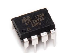
First, ATTINY Atmel chips in DIY audio.  When (small) size matters, these chips are amazing, and amazingly inexpensive. Think of an Arduino the size of an 8 pin op amp!  Yeh!

I have already written about these in this post: introduction, setting them up, how to program them, etc.; as well as this one: Pros and Cons. Why use ATTINY vs. something else? And finally here: interrupts (useful for all Arduino audio DIY perhaps, examples are for ATTINY85).

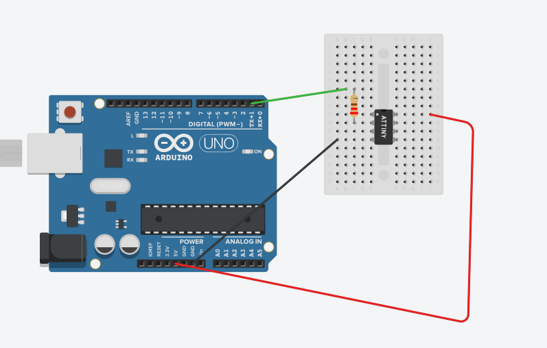
Second: The Virtual BreadBoard (VBB) simulator.  I simulate a CMOS/CV controllable switch toward the bottom of this post.  With the simulation successfully running, I made it into a working DIY synthesizer module with minimal breadboarding.

The 4051 switch

Third: Clamping. What is the best way to get CV or audio into an Arduino Analog in without potentially frying things? (Answer--getting ahead--using zeners is the best thing I could find)

And of course, the inevitable "probably useless to anyone but me" build notes along with photos.  And: the obligatory sound sample of the module: here. The vid below captures a small part of the demo as it was being recorded. You've been warned!


OK let's get started:

In case you don't already know the 4051 CMOS MUX chip is super useful to Audio DIY.  Think of a solid state switch that can select 8 sources and, using 4 logic lines, output the chosen source to a single common pin. Or send the one source to 8 outputs--same idea.

Along with the 4051's cousins, the 4052 and 4053, these are staples of the audio world; you can see the 4051 at work here and here for instance.

But I had never built anything w/ any of them and it was time for that to change.

Along the way there were a few challenges to overcome:

Buffering.You probably won't need to buffer Arduino logic to a CMOS chip, but that's not what we are exclusively doing here. We are connecting analog CV and audio to a CMOS chips' input pins, and it's a fair bet you can't plug a 4051 I/O pin directly into a 120V AC socket and have the IO pin live to tell the tale. To solve this (and no, please don't really plug your 4051 to your house mains, bad idea!) I used a 1N5231 zener diode and op amp.  More in a bit.

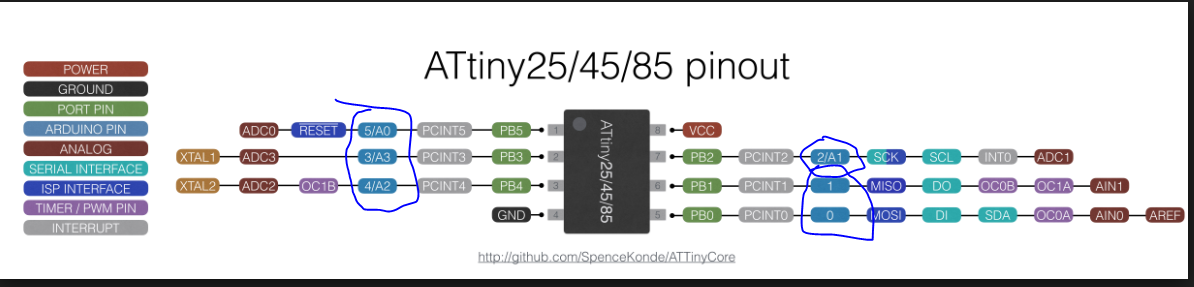
Powering the 4051. Notably the 4051 has 3 power inputs--VSS, VDD, and VEE, for negative supply volts, positive, and ground, respectively.  So you can switch bipolar AC audio through the chip if you set up its power and logic levels correctly.  I don't use bipolar switching for this module but it's good to know you can.

From messing on the bench, the signals sent to VSS, VDD, and VEE determine the amount of voltage needed to equal "HIGH" in digital logic-land. To make this module easier to build I used 0 to 5V to power the ATTINY; logic and power for the 4051 is 0 to 5V as well. I have adequate level shifting and bias voltage offset circuits (previous posts here and here) elsewhere on my modular so this works for me.

But: if I used a 2u panel I would have gone for +5 for VSS, ground for VEE, and -12 for VDD. That allows a 10V bipolar analog signal to get through the switch relatively unscathed. The switch action is still controlled by 5V logic. This is an interesting configuration for future 4051 builds. More at this forum post.

About the module: Design goals are to allow 4 CV inputs switched to 1 output using a pot or 0-5V CV; LED's to display which channel is selected, and use of an Atmel ATTINY vs. all the other Arduinos, comparators, op amps, relays, etc., that could do this. Cram all this behind a 1U FracRak panel. And of course, recycle code from Virtual Breadboard--see the post on VBB here, that's what started all of this.

Block diagram for this module....

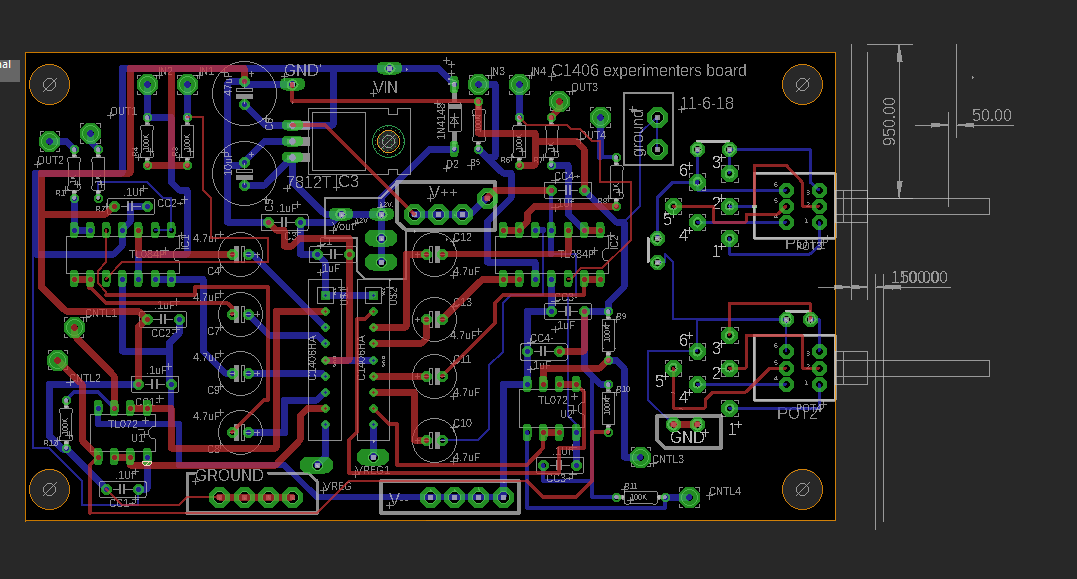
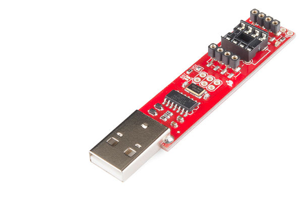
I used a new experimenter PCB for this project. I call the board an "ATTINYfactory" which you can see on my website. The idea is one size fits all for whatever ATTINY DIY audio project I conjure up. Some of them anyway.

If you go to the site, feel free to download the eagle files, send em off to get fabbed etc. if you want, or do whatever. If you use it or modify it please comment below and I'll post whatever you come up with. Or, p-m me: cslammy on the electromusic forum. I can probably send you a leftover if I have one.

For a change, there were no major mistakes on the REV1 board, however, the V+ on the bottom right, directly below the ATTINY chip, is wired for +5V not +15.  Should have labeled that better.....

The "ATTINYFACTORY" board, Rev1.  Rev2 already in the works....

Buffering and zeners. Atmel MCUs will accept decent amounts of current+voltage at their input pins, and can source decent amounts of current at output, but you run the risk of blowing up the pin if you get too crazy. After some discussion with fellow synth nerds and a bit of time on the bench, using a zener diode to clamp the output of an op amp is easy, and can limit current fed into the Atmel MCU to something safe.

The basic idea: slap a 5V zener between ground and the side of a resistor facing away from an op amp:


R6 has to be chosen to not exceed the wattage (V x Current) of the upstream signal, but for most of what we do a standard 1/4 watt 100K is fine. If you don't have 100K, use something bigger--470K or 1M will work. 

The op amp has very high impedance at its non inverting, virtual ground input, so it doesn't care what is upstream really. For this project I used 1N5231's for 5V.  Seems to have worked.

Good news is that 1N5231s are small and were easy to kludge into a quad non inverting buffer.

I just noticed the extra crappy soldering job for IN1, but hey, it works....

I tried other clamps--such as a rail to rail op amps, but they didn't work as well. The easy solution wins out again.

OK time to build--first I drilled out a PCBWAY fabbed "alubase" front panel to accept the LEDs. I used Eagle to create the LED legend at 200mils apart, printed out the legend, and taped it to the front panel.


The input jack and LEDs on the right were fabricated on perfboard.Yes I still use perf.....rarely.
Next, whamboozle it with a drill press:


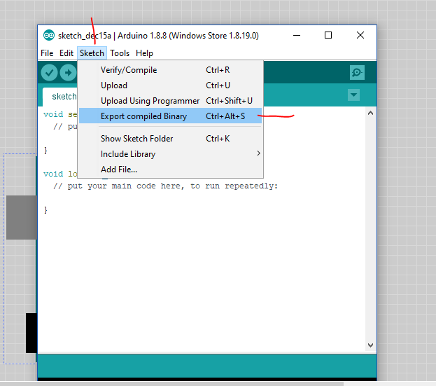
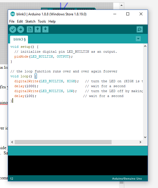
And check to make sure the ATTINY circuit originally crafted on VBB works in the real world when modified for ATTINY...yes, it does!  If you want to review the code it's on GITHUB.


Let's gather up all the daughter boards....I have lots of op amp mini boards already fabbed.


Now it's a matter of assembling all of it, documentation for the entire module is here. Lots of wiring as usual. Easier than creating "skiff" PCBs and then just having to kludge the crap out of it? Because pots go the wrong way? The LEDS light up backwards?  Maybe. Maybe not. A couple of times I wondered "will this ever get done?" because of all the 22 gauge hook up wire used.  I have to cut down on the amount of wire I use in these one-off prototypes!


Test fitting some of the boards.  Will it fit into 1U?
Almost done.  The 4x op amp board fits best in back.  The TL081 output board is soldered to the side.


Christmas Day in the evening I tested the finished module. CMOS.  CMOS run.

One LED didn't work (bad solder to the perf) and I had the CV buffer board VSS wired incorrectly so the A1 pin on the ATTINY wasn't seeing anything at all. Easy to trace the signal with a scope and fix both of these--took only a few minutes. Now it all works.  I just have to Lazertran this and another one is in the bag. This one was fun!

Ready to test....


Update: about the sound clip for this module. I thought the 4051 switch would be good primarily for slowly switching CV's for VCO and VCF modulation but it turns out it's powerful being switched at audio speeds, turning this odd module into a very strange waveform generator (VSWG). 

Everything on the sound clip was created this way. Switch input sources are various combinations of pink noise, mad bees, aconitum noise, a 40106 oscillator,  LFO outputs, ground (so, no sound, causing a gap in the waveform produced), and various DC voltages (so odd square waves are produced) as well as the usual sine waves, ramp, pulse, and triangle. 

To generate the 0 to 5V CV to switch between inputs I used a audio frequency random gate, aconitum noise, a 13700 TH-VCO (ramp worked best; sweeping the 4051 switch CV with audio slowing to low frequency proved interesting), and CV controlled variable tempo square wave LFO's at near audio frequency. The trick seemed to be to make the 4051 sweep through its four inputs hundreds to thousands of times a second vs. just some boring CV at input swept every few seconds. Sometimes in a linear fashion; sometimes randomly.  The 4051 can work fast!  Makes me wonder what an 8 channel version of this would sound like?

As usual no DAW tricks to get this sounding the way it sounds here, this is pretty all my analog DIY synthesizer.  I did roll off some low and high EQ and add a touch of reverb here and there to keep speakers from frying. 

OK that's it for another round.  Not sure what is up next, always so much to do, so little time....I could see doing a 16 channel version of this with CV in (ramp to make it go 1 to 16, sawtooth for 16 to 1? Random for random?and clock in as well; use it as a easy sequencer? As an audio oscillator if you pushed the 4051 to switch really fast? Not sure.

The Christmas holiday is over with New Years coming up. A few more days off work. There was a time when every new years I was out playing, but no longer. Maybe that's for the best, now I can enjoy the holiday at home with my new family. Until next time, Rudolph: it's the holiday--don't breathe the fumes for a change.


Sunday, December 16, 2018

Virtual Bread Board: Simulate Your Trip to the Land of Lunetta

UPDATE: 9-17-23:  I haven't used VBB for a bit; the VBB.exe app mentioned in this post appears to no longer be available.  You now get Virtual Breadboard from the Microsoft Store.

Once installed the new version looks like VBB.exe. You need to pay $30USD to run a simulation (apparently you can lay out parts in the "free" version, but not do a simulation until you pay).

The Windows store version gets (mostly) one-star reviews from its clientele...

what I write below is deprecated....four years is centuries in the computer world.  

As an alternative, wokwi looks interesting. I think I am not going to follow VBB any further.

=============

Howdy again. 


Another post for the world of AudioDIY and Arduino.

This time let's look at a new Simulator I have been messing with called Virtual Breadboard or VBB.

The background:

I stumbled upon VBB while experimenting with some unrelated C programming at my day job. 

VBB is a cool simulator but not nearly as straightforward to use as say Tinkercad--VBB does a lot more, but with the additional features adds complexity.

 The more I use VBB the more I like it....

I wanted to write down how I got VBB to work with the Arduino IDE. Hence this post.

Goes like this:

Tinkercad Circuits is cool but lacks a wide range of CMOS chips to play around with. And you know how DIY folks love CMOS--the 4051, the 4049, the 4066--on and on--these IC's are our friends.  

It'd be nice to have more CMOS SIMs at our fingertips.

For this let's take a look at VBB:

 First the bad news:
  •  For SIMS using Arduino, VBB costs $30 per year. The free version doesn't support Arduino. That may not break the bank--and once you get VBB going you get a hell of a lot for $30 a year--but it's notable that it costs anything at all considering that TinkerCad Circuits is free. But then, this Blog is free as well. Boing!  
  •  VBB is only available for Windows OS. I try to remain positive at all times and as a Linux guy I look at that like this: I figure VBB is maintained by one or two programmers (?), working out of a garage or basement maybe, so don't expect VBB to have an huge army of programmers porting VBB to every platform out there you can think of.  So, Marky Mark: shut up and get Windows going....
  • VBB is not documented well by 3rd parties on Youtube, including some baffling tutorial videos that I couldn't follow at all. I mean what the hell is this? It seems to demonstrate VBB and Arduino, using methodology pretty far from the VBB tutorial, using an Atmel chip that the current software doesn't seem to contain. hello?
  • VBB almost exclusively simulates digital circuits, not analog ones.  There are no op amp chips for instance in VBB. There are in Tinkercad and Fritzing. This makes VBB good for banging together things using CMOS and 74xx chips, but not analog simulations of VCAs for instance. However there is a "function" component in VBB that can be used to (say) add two voltages together--op amp type stuff. Very cool indeed. Maybe a topic for another post?
 Now the good stuff:
  •  VBB includes a whole crapload of CMOS chips to mess with, along with function generators (squarewave only), voltmeters, PWM,  D to A, and other goodies very useful to Audio DIY folk and Lunetta devotees like me:
This is only some of it!!!

  • Like Tinkercad Circuits, you can program your SIM with the Arduino IDE (once you set things up correctly, more about that in a bit.) 
  • VBB doesn't bog down as badly as Tinkercad under normal to heavy use.
  • Unlike Fritzing, VBB is currently maintainedUpdate: wrong--Fritzing has a new release as of Sept 2023 (here).
  • VBB includes a few extremely useful I2C chips for AudioDiWHY in its SIM including the Maxim DS1803 digital pot. Nice! 
  • Since the SIM runs off compiled Atmel binary code, if you can find the library for whatever you are doing, and can successfully compile your sketch, you can probably use it in your SiM.  
  • I wrote to VBB tech support a few times now and the tech there got back to me fast--like, a few times, within an hour. Unusual in the tech support world--hats are off!

SETTING UP VBB

VBB is natively a java app, not C, so you have to tweak things a bit to Arduino C programming going.

Here's the quick way to get this software set up to program using the Arduino IDE--and I will demonstrate by creating the same old tired blinking LED you've probably seen a thousand times.
  • You have to have Windows 8+; I use Windows 10 Pro.
  • Make sure you are using VBB.exe desktop app 6.0.8 or later.  The instructions below may not work with earlier versions
  • Download VBB from MS store. It's free, but to simulate Arduinos (and other popular MPU's) you will need part with some dough....if you are still interested, purchase the $30 a year Proplan.  
  • Create a username and password for the VBB "cloud site", virtualbreadboard.io. You will need these credentials later to launch the desktop version of the software.
  • Download the VBB desktop 6.0.8 app here. For this blog post, we are going to use the desktop version, not the MS store version, of the software.  UPDATE 6-21-19 I have been told the desktop version will be discontinued at some point in favor of the W10/MS store version. I will update this post when I know more.  UPDATE 9-17-23. Yes, only the MS store version is now available, VBB.exe is gone. Oh well.

The VBB "app". Cool, but for this post I focus on integrating the Arduino IDE with the desktop version, VBB.exe.

  • Launch the Desktop version of the app you downloaded.
  • When launching vbb.exe, you will be asked to log into the virtualbreadboard.io site, which will allow the Arduino "add on" license to do its thing.


Next:

  • Download and install the latest Arduino IDE on the Windows 10 system you will use for your VBB simulations. No, VBB doesn't have the Arduino IDE "built in" the way Tinkercad or Fritzing does....you have to install it.
  • On this same Windows system, make sure if you double click a .INO file the Arduino IDE opens, not something else like Notepad or Wordpad.  So create a file called "test.ino", save it, double click on it, and see what happens.  If double clicking an INO file doesn't open the Arduino IDE, follow the directions here to fix it so it does
  • Open up VBB and create a new project, here for almost no reason at all I call it "spanky2"


  • Drag an Arduino into your project:


  • Add an LED on PIN13 and a 1K resistor to ground like this. Note we are using pin 13 connected to the resistor to the LED anode.


  • Highlight the Arduino in your sim, go to the right side of the IDE and click on the 3 dots to the left of the listed "AVR app". You may have to click on "Arduino IDE" or whatever is listed there (might be "sleep") to have the 3 dot icon appear.


  • In the dialog that appears, choose the Arduino icon:


  • Go back to the main view and start the sim by clicking the power icon in the top right:


  • Arduino IDE will open with a blank sketch.  Yeh!


In the Arduino IDE, issue the command Sketch > export compiled Binary:


Go back to the running SIM: The LED should blink, It did for me! Yes you programmed this blink simulation action by creating the hex dump and then having VBB read it--you programmed the SIM with the Arduino IDE.

Cool!!!!

Now make sure you can change things:

  • Go to your Arduino IDE (It's outside VBB--you have to have both running at once--you can alt + tab to it) and change something.  Say make the "LOW" 100 MS sleep but leave HIGH at 1000:


  • In the Arduino IDE, Reissue the command Sketch > Export Compiled Binary


  • This overwrites the hex file that the SIM reads when it runs.
  • You don't have to do anything to VBB--just leave it running. The blinker rate is now 1000 on then 100 ms off, give or take.  The code change will be visible almost immediately--
    "Export compiled Binary" is essentially the same as uploading code to a physical Arduino from your PC.
So here is in a nutshell what you do to change either the components in the SIM or the sketch controlling it:
  • Make changes to the IDE and issue Sketch > export compiled Binary
  • Make changes to the VBB SIM project and file > save 
  • Run the SIM in VBB.  
  • If you're just changing code, you don't have to stop the VBB Simulation; if you want to swap out parts on your virtual breadboard, you will have to stop the SIM, make your changes, and restart the SIM.
  • In any event as long as everything "lives" in the same folder, one component will be in synch with the other.  Go A's!

UPDATE: To further understand VBB, I simulated a 5 Channel 4051 CMOS based audio/CV switcher. Incoming 0-5V CV determines which channel at input is sent to a common output.  This is a very simple circuit if you use an Arduino and was easy to implement using VBB. In a future post I will give more details but the sim looks like this--and I'll try to build a "real" module, that I can use in my modular synthesizer, based on this SIM, in the next few weeks.

UPDATE TO UPDATE!  4051 module is done, heavily based on the 4051 VBB sim you see here, and works great!  See the post here!!!

A slider is used to send 0-5V to A0 of an Uno. 0-1V connects in 0 to the common out; 1-2V sends in 1 to out, and so on.

UPDATE: I got confused by how to see variable values in VBB, display things to the serial monitor, etc. I needed this to debug, but I was overthinking things. It's easy. Hook up the VBB terminal to RX and TX ports as shown below,  RX to TX and TX to RX, set everything to work at 57600 baud, and then use serial.begin etc. for Arduino as documented here. Works great!  


OK enough for one post. Next time (or one of these times soon) I will have more SIMs to show--a CV to 4066 switcher and a trigger delay module, both of which I need in my DIY modular, like, right now.

Until next time, breathe the fumes, but only the simulated ones!


Monday, December 10, 2018

ReverselandFill "Aconitum" Noise Board--Augmented with C1406HA VC Attenuation--Finished!

Hello again fellow readers and audio nerds.  This post: Time to finish off the Reverselandfill "Aconitum" board for my DIY modular synthesizer.

If you want to skip what's below and just hear what the module sounds like finished, that's here.

Also: Part one of this post is here. You are going to want to at least skim the first post or the rest of this one may not make much sense....

Getting to it: after a PCB swap with Reverselandfill's Martijn Verhallen he was nice enough to send me the eagle schematic for his analog noise mixer so I could understand how it works.

His "Aconitum" noise board is designed something like this (it's more complicated, but this is the basic idea):
Simplified block diagram of reverselandfill's Aconitum noise board

An NPN "avalanche" transistor gets sent through a couple of extremely musical passive variable filters, then mixed with two inverting op amp stages in series. There are accommodations for jacks and pots on the PCB, making it a good fit for your Eurorack modular synth.

NB: Martijn must have worked really hard on this design...."box stock" it's a really good sounding board. The filters yield extremely useful timbres for things like rain, wind, surf, everything between, all the way to frying bacon and back.

But "in spite of good tone, I can't leave anything alone?"  For extra headaches I stuck C1406HA attenuator SIPS in series and added a 4th input for external sounds like this:

I could have used VCAs for this.... but trying something new was more torture and thus more desirable.

See more about C1406HA's from my last post about this project; in general the C1406 is an easy to implement voltage controlled dual attenuator SIP IC--in goes audio and CV; out comes audio levels based on CV--the more CV, the more attenuation.  It's like a VCA that can only cut amplitude, not boost it.

One of the challenges for this build (other than some bonehead mistakes on my PCB--more about that in a bit) is that I use FrakRac and Martijn, like many more sane DIYers, uses the much more popular Eurorack format. So I had to piggy back my board below his to make this fit in my rack:


Thank goodness for 4/40 hardware?


Once I got all that bolted together, I separated out the boards and panel and got to work with stuffing and wiring them.

Aconitum board is on the right; my custom panel and quad attenuator PCB on the left.

Let's get building (finally): First I wired up the Aconitum board and powered it up so I could hear it:


Good news here: Martijn's board is flawless--no mistakes--nevertheless, he emailed me a few times to say he is improving it....cool! Martijn also PM'd me to say that he owes the legendary Thomas Henry and Ken Stone for design ideas for the Aconitum board.....if you get your hands on this board, for me it worked with +/- 15V without any mods, even though it's designed for +/- 12V.

Next I wired up my REV1 C1406HA quad attenuator PCB fresh off the DHL boat; and this is where my problems began:

The original schematic--anyone interested, I will post it in Eagle and PDF....


C1406board Rev1: a Plague of Locusts.  Here I've already fixed the power silkscreen issue.....

I rushed this design and fab and made some really stupid mistakes:

  • the V++ and Ground silkscreens on REV1 of the board are drawn backwards. Really?  Um, yep! Traces are OK but the silkscreen says to wire the power supply's V++ to Ground and visa versa.  Doh!! Nothing blew up, but my board obviously didn't work at all until that was straightened out. It took me an evening of head scratching to figure the errors of my ways....it was such a dumb mistake it took me a while to realize, hey, everything is backwards!
  • I forgot to put 100K resistors at the "output side" of the 1406 output decoupling caps. Since these caps are tied to a TL084 (super high impedance inputs right?) there was nowhere for the current to go so the decoupling basically didn't work at all, and I still had a DC offset at output. That's something my first tech boss always told me: always give current somewhere to go!  You'd think after 30 years I'd get this right, but, nope. OK kludged some 100K's on the bottom of the board....now the cap coupling works--fixed.
  • the C1406HA can't really support 10V P/P.  So its input needs to be gained down, while its output needs to be gained up. That remained unfixed; I just have to watch pegging the C1406, but I guess sometimes the pegging doesn't sound that bad (but often it does).  I'll put 6db gain at output I think on the next run. See R21 circled below--this is the standard 6db gain op amp configuration, that's the idea.

Some schematic detail about the resistor issue:


You need resistors R13, R14, R15, R16 to have upstream capacitor decoupling work!

...but my original design was what you see circled in blue, non inverting buffers....which didn't work.


OK I kludged/fixed all those mistakes.  Yes it's a pain to have to kludge prototype boards, but perf boarding all this would have been way more work.....

For those who want to share the pain: I have a revised board ready to be fabbed--as usual, any takers on trying the improved one out? no takers? OK I will get to checking REV2 one of these days, but the REV1 board works, anyway, after I have fixed all the DUMB ASS MISTAKES. I might make a smaller stereo version as well....

Moving on:


I wired the two boards together--a lot of wiring, but nothing too difficult.  

All done but no panel decal; ready for testing

The good news is after all of this I got (I think) some really good sounds out of this board.  Take a listen on Soundcloud here.

Details about the demo:

As usual the demo was made fast, fast, fast.  If I can do this in a few minutes, you should be able to better in say 15 minutes right?

00:00 to 00:28
: Surf part I. Each noise source in Aconitum went though an its internal passive filter then through the Aconitum's built in mixer. The wave crashes were produced by a slow random gate generator which was fed into an ADSR, which was then used to produce CV; that CV attenuated noise ("Tone1") using a C1406HA CV controlled attenuator. Tone1 was set to a very bassy, boomy filter sound. NOTE: I cheated a bit on this one: a tiny bit of phase shifting, reverb and bandpass filtering was used in series with the output to make it the aconitum sound a bit more "other world" but you can get good surf sounds stock right out of box (listen to the last cut of this demo?).

00:30 to 00:45: LFOs feeding the 1406 attenuator. Each of the 3 Aconitum noise sources had a different LFO input attenuating noise. The output of the Aconitum's mixer section went into a vactrol bandpass filter, getting rid of very high and very low frequencies so your speakers and ears aren't destroyed.  With some screwing around I probably could have gotten close to the Apocalypse Now "Helicopter Whup sound", maybe for another day.

00:45 to 01:00 same thing as 30 to 45, but different LFO settings. The "sprinkler" sounds were created by using a CV controlled LFO.

1:05 to 1:30: I put a drum machine snare and kick outs into envelope followers and used that to trigger ADSRs which fed the C1406HA attenuators. The kick and snare noise sounds you hear are substitutes for a 707 kick and snare. The hat sound was fed into the "external" attenuator channel and passed through to the aconitum's mixer.

1:35 to 1:45: A byproduct of setting up the gun range sound (which comes next). Fast Random gates hitting the noise attenuators and also throwing the sound into a stereo panner that was very quickly panning between L and R channels. Produces a frying bacon sort of sound.

1:45 to 2:15:  The gun range. Each output of the aconitum (noise, tone1, tone2) was fed into 3 VCF's and 3 VCA's.  The VCA's were modulated by ADSRs, each of which was driven by its own random gate. this went into an external mixer and into my recorder.

2:15 to 2:40: Same as 00:00 sound but I changed parameters to make it sound more like traditional surf.

BACK TO THE BUILD: Final step after testing and seeing what it can do was to decal it.  


Ok that's it for now.....Overall this modified board swap module was a lot of work but I had a lot of fun building it, and it's already become a really useful addition to my DIY modular synth. I think it sounds really good!

Not sure what I will work on next but the MCU world is calling me again. My girlfriend (who btw is a mental health professional) says I have become too obsessed with DIY, and I need to take a break, so I am almost done w/ week one of a two week lull.  Did I breathe too many fumes? Maybe! And always remember: "Sanity is relative".

Thursday, November 29, 2018

FrakRac +/- 15V Power Supply, drop in Replacement for the Original

Hi again: Quick one this time.

When it came time to pick a format for my modules, I had a lot of choices: Doepfer's "Eurorack"; "5U"; and so on.  I went a bit outside (I do that sometimes?) and chose PAIA's offering, FracRak.

Maybe because it's about the same physical size as the API 500 "Lunchbox" format; I used 500's a lot during my audio engineering days, and found that the 500 series is a good compromise in size--the knobs aren't super tiny and the panels aren't super huge. With Frak or the 500 series you can throw your rig on the front seat of your car without issue, or just get your girlfriend to carry it on her lap. Just skip the Taco Bell drive thru!  Try doing that with a Moog 55, right?

Or maybe because a PAIA 2700 kit got me into this whole thing to begin with when I was like 12?

Because I spoke to John Simonton in 2005 and he was one of the nicest guys you could ever talk to?

All of the above I guess.

OK good news is that Fracrak is cheap n easy as far as building up a case and power supply. But I wanted something a bit beefier than PAIAs "wing" 9770 supply.

So I whipped up my own drop in replacement for powering FrakRacs:


The clone board--bolt it right into your FrakRac case.....
My design has the advantage of being able to add heat sinks then screw them down to the PCB vs. have them "flap in the breeze", offers a bit more cap filtering options, slightly better reverse voltage protection for the regulators and some other basics. This is a $5 for 10 PCBs fabbed in china type deal--why not? It probably won't work for super-critical applications, say a giant bank of analog VCO's. For that you may need better regulation, but for most modules this quick replacement gets the job done.

the original PAIA supplied PCB.  Super low parts count--them Voltage Regulators are flapping in the breeze....

For this power supply you can get more information on my website including gerbers, PDF of schematic and board layout, BOM etc.


OK, If you go the Frac route like me and want something more stable/better for VCO's let's say, I'd suggest sticking to PAIA's 9771 Psup...maybe I will modify the design above for more beef as well....that said I have built this board several times now and have successfully mounted it inside some of my FracRak cases. Works.....no magic smoke, no ripple, no big problems after many many hours of use.

About the board: The cap values are not critical here--I have used 1000uF, 2200uF or 1500uF for C3-C4, 470uF or 100uF for C2-C6, left off C1 C5 entirely, used 100pF for the caps close to the output headers, etc. I mostly use whatever I have in my junk box that's reasonably close value wise to what's here. Good enough!

OK enough for this time. Frak well and live!

Coming soon: More noise projects with voltage controlled attenuators.

Friday, November 16, 2018

Synth Gates, Interrupts, and Arduinos; a Million and One Uses

Yes once again: more Arduino Control Voltage Fu.

Continuing from last time...I am focusing on another corner of the Arduino for audio world:  interrupts. The idea; your code is running, we want to interrupt things (say, a note has just been pressed) and have something happen (say, play a note). When you are done, go back to whatever you were doing (like, wait for another note).

With further ado: the coding examples here were tested on an ATTINY85. All the interrupt information you see is available for most if not all Arduinos but the code will be different (because, for instance, a Nano has more than 8 pins).

Goes like this: When I started using Arduinos for Synth DIY, it quickly became clear I needed to figure out a good way to accept a gate input signal and control my code with it. Duh! We synth guys use 0-5V gates all over right?  But let's not create a loop like this: did someone press a key yet? No? How about Now?  No! Um, Now?  No!!!! Now?  Yes!!!! Etc. all that waiting around ends up sounding, well, not very musical.

Instead, you want to press a key, and then as close to real time as possible, you want something to happen.

So: what's a really good way to do this? Use interrupts....specifically change pin interrupts--then using a boolean variable to trap if the gate signal was going from 0 to 5V or from 5V to 0. That worked great for me.

Turns out it's not hard to stick all of this into your ATTINY85 sketch, once you know the secret:

First declare this:

void setup()
{

    // (pin declarations, variables, whatever blah blah....
    //but then this...

    GIMSK = 0b00100000;    // turn on pin change interrupts
    PCMSK = 0b00010000;    // turn on interrupt on ATTINY pin PB4
/* you can enable more than one pin for this.....
 a "1" in the above PCMSK line means use pins as interrupts, following this logic: 0bxx54321 where
the "54321" business are physical pins on an ATTINY. 
*/

    sei();                 // enables interrupts


Wait a minute, what are "pin change interrupts"? Information is here but: Easy! 

That means, you're using external hardware interrupts--change the voltage present at this pin, relative to ground, and you can immediately change what your Arduino is doing.

Added bonus: with "pin change interrupts" you can pick the pins you want to use for interrupts. Including more than one or two or three pins on the same chip at the same time. And, depending on the Arduino you use, the pins allow you create up to 3 completely independent interrupts, each of which can do something different! Handy!

BTW, an incredibly good explanation of the the Arduino interrupt universe--from the Atmel ATTINY to the big huge crapping ones--is here.

(The "change pin" moniker threw me for a bit. Shouldn't it be a "pickyerown" interrupt? Whatever.)

OK after your GIMSK PCMSK  etc. you have declare an "interrupt vector"--this tells the ATTINY what to do when the interrupt is thrown.

Here I am reading whatever voltage is present at PB4 pin and assigning it to "gatemaker", a boolean variable I do declare.


void setup()

volatile boolean gatemaker = LOW;

// blah blah, other stuff here....

ISR(PCINT0_vect)
{

     gatemaker = digitalRead(PB4);
}

This code can thus act on incoming data--a gate rising edge, a new midi note on, etc., fast--very, very fast. More musical!

So--do that like this and this like that:

void loop()

if (gatemaker == LOW) 

 // I see a falling edge, 5V to 0V, on my gate signal.  When I see that:

///do something; charge a cap, turn on an LED, change pitch, //whatever.....
}

//but if I see 0V to 5V......

if (gatemaker == HIGH)
//do something even still more different; discharge a cap, turn off //an LED, don't change pitch, whatever.....
}

Wow! That's really easy! A million and one uses: ARs, gate to trigger, trigger delays, on and on. Trap when your gate signal is going up or down, then do something fun. NNNNNNext!

Again this is useful for ATTINY but by studying Arduino coding on line can be done with all the chips I've seen in this large family--so, whatever other Arduino widget suits you.

This ATTINY methodology took me a few evenings to figure out, mostly because there are so many different documented ways to get at the interrupt paradigm, but this whole change pin interrupt/boolean method seems to work every time and is simple, simple, SIMPLE!!! For the Nano, there are two pins already all set for interrupts, and the code needed is the usual super simple stuff we all expect here in Arduinoland.

Back to Audio: Final thing to do is protect your ATTINY interrupt pins from an obnoxious gate signals from (say) your 15V power supply (oops!  Patched my modular wrong....blew up that ATTINY....magic smoke....yeh baby yeh!)

For that I used this circuit fragment plugged into the PB4 pin used above; as always, many ways to do this, but this simple NPN circuit fragment worked for me. Transistor is a 2N3904....this inverts the gate, so you have to code accordingly.


OK for now that's it. I created an ATTINY based module I call "ConBrio" allowing a gate to speed up up up or down down down. It uses this whole pin Change interrupt thing extensively. It works on the bench but I am trying to make it "more musical" whatever the hell that means. I figure I will finish the code and hardware for that and post it soon.

Until then, don't breathe the TINY and have fun!!!


Thursday, November 15, 2018

ATTINY arduino for AUDIODIY--Pros and Cons--Debugging these Tiny Spuds!

From last time: I am waiting for C1406HA voltage controlled attenuator boards to arrive from China to get reverselandfill's noiseboard going.

Any day now....

 In the meantime I thought I'd keep working on my Arduino skills, this time working with an ATTINY85.

Part one of my ATTINY exploration is here.....


Cutting the BS and getting to it--pros and cons w/ working with an ATTINY vs. all the other Arduinos out there.  Why use it at all?

Pros:

  • ATTINYs are super cheap. I bought 4 of them for $12 on eBay.  If you can work with SMT, it's even cheaper.
  • They are super small. Tiny? Sure. In Eurorack land where everything needs to get tiny, that's good.
  • You can program a few of them to do the same thing and then drop them into your projects like you just fab'd up custom IC's. Gate to trig? Gate delay? One Chip LFO?  Yep.  
  • Most all the important commands you can get out of a Nano or whatever are supported here.  Pin change interrupts for instance?  Yep. I'll get into that in the next post, which I'll upload tomorrow.
  • You can get an all in one programmer for about $16 USD complete with handy built in blinking LED.  But watch out for this gotcha....this one drove my crazy....on Linux or mac programming code into an ATTINY works OK. Then suddenly quits. Like you unplugged the programming board...but you didn't. Why? Turns out to be a USB permissions issue. To fix follow the instructions in this link or just do this : open your terminal and run lsusb from terminal. Then chmod the crap out of the usb ports with this: sudo chmod 666 /dev/bus/usb/0xx/0yy where xx and yy are the device ID's used for the ATTINY programmer.  You can make that change permanent by following the advise here.  Otherwise the "write to chip" commands in Arduino IDE become caloric; i.e., they donut work.


The AVRTINY programmer.  $16USD!!!


And now....Cons:

Biggest issue, con number one! There is no easy way to debug these damn ATTINY rascals.

What does this mean?

On the Nano, you use serial print commands for this, to see if a variable is working the way you want, for example:


void setup()
{
  Serial.begin(9600);
}
x = 100; // or whatever other bozo value you are trying to determine

Serial.println(x);
delay(2000);


If you expect to see a 100 here and get 0 in your serial monitor, that tells you you screwed up your code!

On the ATTINY, this debugging methodology is not so easy. That's because serial commands are not supported by default at all!

The workaround: There are lots of fixes for this. After digging I found a nifty add-in library called TinyDebugSerial. I liked it because it was easy to implement. And if you read this blog at all you know I like easy.

You can get the add-in here.

Drag the files into your Arduino library folder, then try this as code:


 #include <TinyDebugSerial.h>

void setup() {           
 #include <>TinyDebugSerial mySerial = TinyDebugSerial();
mySerial.begin(9600);

}

void loop() {
mySerial.println("hello world!");
}

OK, serial print data, streaming at 9600 baud, now shoots out ATTINY85's "pin PB4" (that's pin 2 for those of us in the DIP8 real world). In this case "hello world" over and over.

But....Where to hook up the TX out? So you can read it, Elmo??

I ran it to a RX pin of an Ardino UNO via a 220 ohm resistor--hooked the UNO up to a 2nd USB port in my Linux laptop--fired up a new IDE window for the UNO--set the USB port in the IDE for the uno--and (finally) read the serial strings out of there. Worked!

Using an UNO to get tinydebugserial output from an ATTINY.  Wire it like this....

Con #2:
there just aren't that many pins to work with. This is an 8 pin chip and 2 of them are for power.  1 more is for reset, and it can do other things, but not easily. Not much more to say there. Sorry.

Con #3: the pinout designations are odd for ATTINY.  I found for analog in I had to use something like "A0", "A1" etc. For digital I had to use "3". I had to check the pinout diagrams online more than a few times, and for me, screw around a bit....

For instance, analog Pin A2 is tied to physical pin 3 and A3 is tied to physical pin 2.  But why, Scottie, why?


Con #4: ATTINYS are slow, slow, slow, SLLLOWWW and then they are slower than snot!

Overall--I almost gave up a few times--really, for audio DIY why use ATTINY at all and not just a Nano? Or Uno? Or Due? Or  Dookay?

Not sure I can answer that....but then I came back to it...I bought the damn tiny things--I just have to figure it out.

After a few evenings I did get it working, and with debugging set up could start to do useful things. So yes there are probably more cons than pros. I programmed it anyway. Guess it's just the way I am.
Doesn't mean you have to be that same way.

Soon to come--using interrupts to track CV gates with these little turds.  Until then.....well you  know.

Anything to Clock Subcircuit

Readers:  If you want to build the project featured in today's post, please go to  PCBWAY's  Community pages --a gerber ready to dow...