Saturday, October 24, 2020

Probe Me Up Scotty: Super Useful, Super Simple Audio Signal Tracer


Hello?

Here's what's up. I saw a nifty bit of Heath kit used on a favorite YouTube repair channel: "Shango066". This guy fixes tube TV's and uses old test gear to do it; he uses a Heathkit Signal Tracer. When he's trying to find fault in a tube TV's audio subsystem, he cranks up the Heathkit then touches its probe to various audio circuit points, trying to figure out what's working and what isn't (fearlessly I might add--Shango is relaxed around lethal circuits--don't those old TVs have like 12-20KV inside of them? And you thought working on a Fender Twin was dangerous, right?).

If you do this in a logical way an audio/non DC type fault can be teased out fast.

I need one of these! 

Should I buy one? Hmmm. Mr Carlson sells one (vid here), and you can get a nice one from Rattlesnake and of course used Heathkits and Eicos are on sale from time to time on Ebay. 

But can I DIY something to help me DIY? Why not? I started to look around on the Internet about how a signal tracer works, and turns out, it's really simple; all you need is this:


The probe lead itself can be anything--cut up an old lead left over from a discarded DVM for instance?

I dug a 1.5mm male contact pin out of the junk box and soldered a 22 gauge wire to it, then covered it with shrink. Good enough. 

If you don't have a .1uF cap around, well, I don't know what to say. Your junk box sucks? That's used to block DC. Yes, you need this.

The output can be 3.5mm, banana, or whatever. I chose a 3.5mm jack because I have about a million of them and my bench setup (post here) has a 3.5mm mono input to a BGW 19" 1U stereo audio amp. Then I added wire loops anywhere I thought I might want to clip an alligator lead.

It took about 15 minutes to solder onto Perf:

Pass the ProbeUsing the PMUS is super easy, doo-han. Hook GND up to a suitable ground source, plug the 3.5" output into an audio amp.

Next: plug or clip a 1K signal in to the audio input of the circuit under test. 

Finally, get your hands on the schematic for the gizmo you are repairing and follow its audio path with the probe lead. When you hear a 1K test signal on one side of a component and zilch on the other, that will probably tell you a whole lot about where the fault starts.

PT2399 circut--the pots at the top of the board did zilch. And it helps to put in IC's right? Stuffed it, Probed it, fixed in like 2 minutes!

I used this simple probe just now to troubeshoot a PT2399 circuit with a dead internal mixer. Yeh!! Could I do the same with a scope? Of course, but touching the PMUS audio probe to each contact and hearing 1K audio then moving on to the next part solved the problem a whole lot faster--turns out, I had a dicey solder joint on a 1K resistor right after an op amp's output.  

There are all sorts of Interweb variations of the PMUS idea--basic how-to (here); same idea with a 386 amp (here) for instance. You get the idea.

This is going to change how I troubleshoot things, and why I didn't build this like 10 years ago is a mystery I may never solve. Run, don't walk to your junk box, switch off your Enterprise's shield, and perf this up. 

Monday, October 19, 2020

Stomp-Synth Adapter--All Hail Ken Stone!

Simple one this time: I needed to hook up some of my old guitar stomp boxes to my modular rig. How to do that? It's a simple attenuator (to not overload the stomp's audio in) and then op amp boost.  

Two finished stomp adapters.  Front panels are PCB material covered with Mr. Label

You guitarists already have a ton of stomps right?  I do....some of them dating back to my high school days.....so let's get em hooked into our modular setups.

Yes that's a 1970s era Deluxe MM.  Collectable! Yep, my DIY skills in 2002 were pretty NG, but these old stomps still work. Bonus points: see if you can guess which of the stomps here are hand made?

Sure I could have designed and breadboarded something, but why do that when Ken Stone has already done the heavy lifting?

Enter Mr. Stone: If you've built synthesizer circuits before you may have already run into Ken Stone's work. His designs have been present as long as I can remember. 

He got out of the PCB shipping business (understandably) and gave it all over to Elby Designs, you can find that site, and Mr. Stone's boards for sale, here. I find myself studying Ken's designs all the time; they are practical, the ones I've built always sound good, and are well documented. Yeh!


The schematic for this post is very close indeed to Ken's CGS-60 circuit, with a few minor mods to accommodate frac setups--the form factor sold by Elby didn't look like it was going to fit into my rack, but it's easy enough to lay out a new board, then off it goes to the fab shop (here). Gotta love that CGS "floating ground" design. Ken crafted all sorts of cool stuff including some licensed Serge circuits, right? Right! all hail Ken Stone!

As Ken says via the Elby site, if you build this, expect to have to mess with R3/R7 to adjust output gain and maybe screw a bit with the attenuation subcircuit to process input, but really that's easy--it's changing 2 values essentially. I am using 10K now but will probably go for 4.7k soon since right now I'm getting too much gain. UPDATE: for my 10V P/P synthesizer, using 4.7k for R3/R7 and A10K pots for FXLEV1 and FXLEV2 did the trick. Your setup may require different values.

Poof, back from China, let's fab and build it:


Let's forget the rest of the build photos, you've seen this before? Here it is with crap front panel, ready to go into the rack for further refinement:

But does it make balloon animals?


So far so good, but there were enough dumb mistakes on the rev1 pcb that it will have to get a rev2 pcb fabb'd. 

The mock up w kludge fixes works great, no smoke yet, and this basic design opens a whole new world of stomps and synthesizers living together in double happiness. 

Once that's sorted, I'll build the Rev2 PCB up and see if it works. Update 10-28-20: rev2 is back and I am fabbing it now. Stay tuned....UPDATE 11-5-20. REV2 here and works.  See photos of finished units at the top of this post. 

UPDATE 11-6-20: Go to the Elby site here if you want to build the real CGS060/CGS360, otherwise if you want copies of my eagle or gerber files, comment below.

UPDATE 10-30-24 As per comment--I emailed Elby to see if it's OK to post the sch, brd, and gerber for this post's project. Elby gave me the OK--but I need to be clear: what you get from my github is a board and design inspired by CGS060/CGS360, it is not the official CGS060/CGS360 board. Also, my version is for large format/Frak. 

The github repo with the AudioDiWhy stomp adapter is here.

Yep I'm echoing and delaying and will continue to do this over and over. Until next time, Don't breathe the fumes.

Sunday, October 11, 2020

Creating Blinkenlights using PyGame

From last time: I'm beginning to a trip down the retro computing rabbithole, and what can be more retro than "Blinkenlights"?

I mean this!


....when the computer does something we flash a whole bunch of lights. It's that easy: I/O? sure.  Register contents? Data and Address lines? Uh huh. "AQUS." "APRES" "CACN"  "CAPR" etc?  Don't know what the hell it means, but, yep.

The primary goal for Racduino: see what data and address lines on the RCA180x are doing with minimal effort when stepping through machine code instructions. It would be not too hard to use LEDs or even small incandescents for this, or an MSO, but I don't want to spend too much time wiring and then rewiring a small element of a larger project.  

Let's use Python and a Raspberry Pi instead and get it done.


My simple dev platform: Raspberry Pi4B, Thonny Python interpreter, keyboard/mouse, and the good old MacBook Pro (Sierra!) for serfing while I work. The board on the right is perf and has pots and momentary switches, wired to dupont type female connectors. For this proof of concept it's used to pull Pi4's GPIO pins to ground (details of Pi4 pullup/down is here).  The larger 23" monitor will be replaced with something much smaller sometime soon.

So how does it work? You can spend a lot of time on the exact look and feel of your Blinkenlight masterpiece, but today this is just a POC, with 5 pins, one rectangle, and one bit of text.

Here's a screenshot with all GPIO pins at +


Now let's pull pin 3 to ground.


Now pins 2 and 3:


You get the idea. 

There are undoubtedly a lot of ways to do this, but for whatever reason, the pygame module seems to work for me. I had never heard of pygame before this project, but the POC code below took minutes to code!  Pygame is easy and well documented. Why not.

OK heres the POC code; when this a lot closer to done I'll git-it.

##########################################

import pygame
import os
from time import sleep
import RPi.GPIO as GPIO
 
#for this dictionary key is GPIO pin and list is
#x,ylocation on screen.  Top left in pygame is 0,0
# positive Y values are LOWER (as if negative).

led_map = {2:[40,40], 3:[70,40], 4:[100,40],5:[130,40],6:[160,40]}
 
#Setup the GPIOs as inputs with Pull Ups since the buttons are connected to GND
GPIO.setmode(GPIO.BCM)
for k in led_map.keys():
    GPIO.setup(k, GPIO.IN, pull_up_down=GPIO.PUD_UP)
 
#Colours
WHITE = (255,255,255)
BLACK = ( 0,0,0 )
GREEN = (0 , 255, 0)
RED = (255,0,0)


os.putenv('SDL_FBDEV', '/dev/fb1')
pygame.init()
pygame.mouse.set_visible(False)
screen = pygame.display.set_mode((700, 500))
screen.fill((255,255,255))
pygame.display.update()

#draw background.
pygame.draw.rect(screen,BLACK,(2,2,200,70),1)
pygame.display.update()

#add text
myfont = pygame.font.SysFont('Courier', 20)
textsurface = myfont.render('PI4 GPIO', False, (0, 0, 0))
screen.blit(textsurface,(50,80))
pygame.display.update()


#draw blinkers
def ledsmall (color, loc1, loc2):
    pygame.draw.circle(screen,BLACK,[loc1,loc2],10)
    pygame.draw.circle(screen,color,[loc1,loc2],9)


while True:
    # Scan the buttons
    for (k,v) in led_map.items():
        if GPIO.input(k) == False:
            a = v[0]
            b = v[1]
            ledsmall(RED,a,b)
        else:
            a = v[0]
            b = v[1]
            ledsmall(GREEN,a,b)
         
         
            pygame.display.update()


#####################

I won't go through line by line what this does--I think if you are OK with python it should be pretty self explanatory. If you have questions or can think of improvements comment away....The led_map dictionary captures the GPIO pin as the key and the location of the graphic in a 2 member value list.  Want more LEDs?  Add to this dict. 

It seems fast, bug free, and so far, good enough.

So what's next?  Don't know, but if you need inspiration for your own virtual blinkenlight fiasco (as well as a lot of fun with retro computing props and a great waste of about 6 hours during covid), subscribe to netflix, and have a bunch of time to kill, take a look at the mini-series "Maniac".  

Freeze frame any time you see blinkenlights--there are a many a'blinkin, and then try to name all the other retro computing crap you see on screen--endless fun right? 

I think I see a PDP10, or maybe it's an 11? 70's era video consoles, analog video patch bays, old hard drive caddies, Mono CRT monitors, and on and on. The director said "I want more blinking light!" so I figure the art department had a lot of fun with this. 

And, Emma Stone is foxy to boot. See you next time.

Saturday, October 3, 2020

RACduino? What the heck is that?

Update 10-31-20: this entire post is stupid, because the Racduino has already been done! 

I found the project here while I was searching for a decent 1802 emulator.  Yo!

The linked project even has a better name. 

Anywhere, here's my post on the same damn idea: I am beginning to compose a great acoustic guitar/strings/voice tune; I'm going to call it "Eleanor Figby".  Oh well.

All this shelter in place stuff leaves me with way too much time on the weekends. What to do? See a movie? Nope, closed, Elmo. An A's game? Um, no--stadium is shut tight, and I don't get cable. Write songs/complain about covid/drink wine/eat pizza with my old fart rock and roll buddies? Sorry, can't. We are all afraid of losing our sense of smell, and then, without noses, how can we enjoy Neil Diamond

No ankle bracelet but we are all under house arrest. That's the ticket: Kill time! 

Enter the RACduino--my first machine code project ever. If that won't make the shelter-in-place-we-all-are-under-arrest OCD hours drop to nothing (like 80's one hit wonders) I don't know what will.  

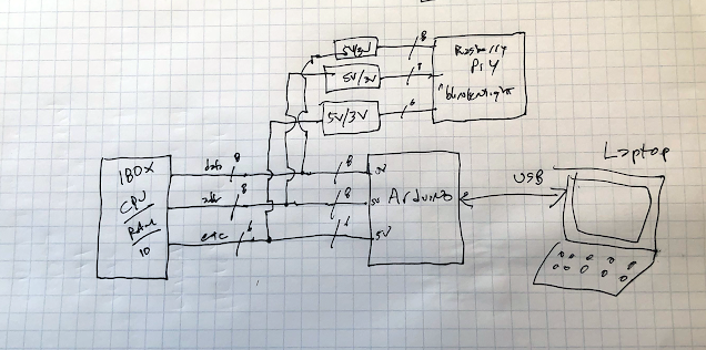
"Let's get started". To postulate:


Drawing out the idea:

What's all this then?  The CPU on the left is an RCA180x--probably a 1806. Can I make it a tiny bit like a modern MPU? To find out, I could buy an RCA180x experimenters board and start coding right?  Nope. Too easy! 

Following the flowchart above I'll toggle the various data, address and other lines with a "real" Arduino (cheating kinda, but hey it's still outputting machine code) and just for S&G's set up a blinkenlight display on a paralleled Raspberry Pi4 with pygame Python code.

Best of all--the 180x RCA CPU may be the easiest chip in the world to write machine code for. So I think this is doable!!

Machine code--What? Yes, after working on computers for over 35 years, who knows how long, forever, it's time to finally see if I can get something working (anything!) blasting instructions in with 1s and 0s only, no assembler, no C, no Arduino IDE. Old school--real old school. So about the name: RCA is easily scrambled to RAC, and maybe I can get this machine code beast working a tiny bit like a modern MPU, say, Arduino?  Or I could fail. Go A's! Racduino!


1806--a great year right? Why this and not say a 6502?  For one, my neighbor and fellow DIYer mcvl had a few 1806's lying around and loaned (gave?) them to me. Score! BGmicro also had some 1802's on closeout so I got a few more. Trying to keep things simple: The instruction set for 180x seems easy, relatively finite and well documented. Also, it's easy to find simple hardware implementations for this CPU family.  Yep I am starting there.

OK, What else is needed? 


Digging around I found more dookies that might be useful for the RACduino in my junk box like ROMchips, static RAM and other things. MVCL also contributed. Will they be used? Who knows?


The RCA CPU is a 5V CMOS beast, but the PI4 is 3.3V, so I got a few TB0104 converters from Sparkfun.....TB0104 has 101 uses....details about this part are here.


PI-HOLE? Getting the PI4 hardware going was not as easy as I thought it'd be. The main thing I stumbled on was getting a damn SD card set up with a working, bootable OS. I ended up following the instructions here (Scroll down to the "do it yourself using NOOBs section") which worked, but it took me an evening of SD cards just not doing a thing--perhaps I was rushing. That's why it took me a whole evening. 

With that out of the way, I got the basics of the Pi4 GPIO/blinkenlight python code working, but I have to refine it a bit. Maybe next post. But overall, all good news--PI-os is Debian like (easy) and has gud-enuf  Thonny already installed. The pygames module imported no sweat on the PI4 using PIP.  We're cooking with oil!


The last thing needed is a CPU clock and stepper, I found an easy 3x 555 CPU clock design from legendary YouTube nerd Ben Eater. I unabashedly stole his design put it onto a PCB. (actually BE's entire breadboard computer series on YT--here--got me started on the retro-machine code path--check it out, Ben Eater rules the school--great stuff!)

Will any of it work? Does Doris get her oats? The jury is still out. Assuming I can get this working at all, I need to think about what to do with it, DIY or audio DIY wise, but to start I'd be happy just blinking an LED. 

I doubt the racduino could ever come close to a Pro Micro, but then again, what does? So this is primarily a learning experience for me, but that can be said about all of this.

OK, plenty of Part IIs part IIIs etc coming up.  I don't think I'll work on this one straight through however--doesn't matter, since over the past 8 months or so I've lost track of time. See ya!


JTAG to SWD Converter

Readers: If you'd like to build the project featured in today's post, please go to PCBWAY's Community pages--gerber file, KiCAD ...