Thursday, November 29, 2018

FrakRac +/- 15V Power Supply, drop in Replacement for the Original

Hi again: Quick one this time.

When it came time to pick a format for my modules, I had a lot of choices: Doepfer's "Eurorack"; "5U"; and so on.  I went a bit outside (I do that sometimes?) and chose PAIA's offering, FracRak.

Maybe because it's about the same physical size as the API 500 "Lunchbox" format; I used 500's a lot during my audio engineering days, and found that the 500 series is a good compromise in size--the knobs aren't super tiny and the panels aren't super huge. With Frak or the 500 series you can throw your rig on the front seat of your car without issue, or just get your girlfriend to carry it on her lap. Just skip the Taco Bell drive thru!  Try doing that with a Moog 55, right?

Or maybe because a PAIA 2700 kit got me into this whole thing to begin with when I was like 12?

Because I spoke to John Simonton in 2005 and he was one of the nicest guys you could ever talk to?

All of the above I guess.

OK good news is that Fracrak is cheap n easy as far as building up a case and power supply. But I wanted something a bit beefier than PAIAs "wing" 9770 supply.

So I whipped up my own drop in replacement for powering FrakRacs:


The clone board--bolt it right into your FrakRac case.....
My design has the advantage of being able to add heat sinks then screw them down to the PCB vs. have them "flap in the breeze", offers a bit more cap filtering options, slightly better reverse voltage protection for the regulators and some other basics. This is a $5 for 10 PCBs fabbed in china type deal--why not? It probably won't work for super-critical applications, say a giant bank of analog VCO's. For that you may need better regulation, but for most modules this quick replacement gets the job done.

the original PAIA supplied PCB.  Super low parts count--them Voltage Regulators are flapping in the breeze....

For this power supply you can get more information on my website including gerbers, PDF of schematic and board layout, BOM etc.


OK, If you go the Frac route like me and want something more stable/better for VCO's let's say, I'd suggest sticking to PAIA's 9771 Psup...maybe I will modify the design above for more beef as well....that said I have built this board several times now and have successfully mounted it inside some of my FracRak cases. Works.....no magic smoke, no ripple, no big problems after many many hours of use.

About the board: The cap values are not critical here--I have used 1000uF, 2200uF or 1500uF for C3-C4, 470uF or 100uF for C2-C6, left off C1 C5 entirely, used 100pF for the caps close to the output headers, etc. I mostly use whatever I have in my junk box that's reasonably close value wise to what's here. Good enough!

OK enough for this time. Frak well and live!

Coming soon: More noise projects with voltage controlled attenuators.

Friday, November 16, 2018

Synth Gates, Interrupts, and Arduinos; a Million and One Uses

Yes once again: more Arduino Control Voltage Fu.

Continuing from last time...I am focusing on another corner of the Arduino for audio world:  interrupts. The idea; your code is running, we want to interrupt things (say, a note has just been pressed) and have something happen (say, play a note). When you are done, go back to whatever you were doing (like, wait for another note).

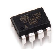
With further ado: the coding examples here were tested on an ATTINY85. All the interrupt information you see is available for most if not all Arduinos but the code will be different (because, for instance, a Nano has more than 8 pins).

Goes like this: When I started using Arduinos for Synth DIY, it quickly became clear I needed to figure out a good way to accept a gate input signal and control my code with it. Duh! We synth guys use 0-5V gates all over right?  But let's not create a loop like this: did someone press a key yet? No? How about Now?  No! Um, Now?  No!!!! Now?  Yes!!!! Etc. all that waiting around ends up sounding, well, not very musical.

Instead, you want to press a key, and then as close to real time as possible, you want something to happen.

So: what's a really good way to do this? Use interrupts....specifically change pin interrupts--then using a boolean variable to trap if the gate signal was going from 0 to 5V or from 5V to 0. That worked great for me.

Turns out it's not hard to stick all of this into your ATTINY85 sketch, once you know the secret:

First declare this:

void setup()
{

    // (pin declarations, variables, whatever blah blah....
    //but then this...

    GIMSK = 0b00100000;    // turn on pin change interrupts
    PCMSK = 0b00010000;    // turn on interrupt on ATTINY pin PB4
/* you can enable more than one pin for this.....
 a "1" in the above PCMSK line means use pins as interrupts, following this logic: 0bxx54321 where
the "54321" business are physical pins on an ATTINY. 
*/

    sei();                 // enables interrupts


Wait a minute, what are "pin change interrupts"? Information is here but: Easy! 

That means, you're using external hardware interrupts--change the voltage present at this pin, relative to ground, and you can immediately change what your Arduino is doing.

Added bonus: with "pin change interrupts" you can pick the pins you want to use for interrupts. Including more than one or two or three pins on the same chip at the same time. And, depending on the Arduino you use, the pins allow you create up to 3 completely independent interrupts, each of which can do something different! Handy!

BTW, an incredibly good explanation of the the Arduino interrupt universe--from the Atmel ATTINY to the big huge crapping ones--is here.

(The "change pin" moniker threw me for a bit. Shouldn't it be a "pickyerown" interrupt? Whatever.)

OK after your GIMSK PCMSK  etc. you have declare an "interrupt vector"--this tells the ATTINY what to do when the interrupt is thrown.

Here I am reading whatever voltage is present at PB4 pin and assigning it to "gatemaker", a boolean variable I do declare.


void setup()

volatile boolean gatemaker = LOW;

// blah blah, other stuff here....

ISR(PCINT0_vect)
{

     gatemaker = digitalRead(PB4);
}

This code can thus act on incoming data--a gate rising edge, a new midi note on, etc., fast--very, very fast. More musical!

So--do that like this and this like that:

void loop()

if (gatemaker == LOW) 

 // I see a falling edge, 5V to 0V, on my gate signal.  When I see that:

///do something; charge a cap, turn on an LED, change pitch, //whatever.....
}

//but if I see 0V to 5V......

if (gatemaker == HIGH)
//do something even still more different; discharge a cap, turn off //an LED, don't change pitch, whatever.....
}

Wow! That's really easy! A million and one uses: ARs, gate to trigger, trigger delays, on and on. Trap when your gate signal is going up or down, then do something fun. NNNNNNext!

Again this is useful for ATTINY but by studying Arduino coding on line can be done with all the chips I've seen in this large family--so, whatever other Arduino widget suits you.

This ATTINY methodology took me a few evenings to figure out, mostly because there are so many different documented ways to get at the interrupt paradigm, but this whole change pin interrupt/boolean method seems to work every time and is simple, simple, SIMPLE!!! For the Nano, there are two pins already all set for interrupts, and the code needed is the usual super simple stuff we all expect here in Arduinoland.

Back to Audio: Final thing to do is protect your ATTINY interrupt pins from an obnoxious gate signals from (say) your 15V power supply (oops!  Patched my modular wrong....blew up that ATTINY....magic smoke....yeh baby yeh!)

For that I used this circuit fragment plugged into the PB4 pin used above; as always, many ways to do this, but this simple NPN circuit fragment worked for me. Transistor is a 2N3904....this inverts the gate, so you have to code accordingly.


OK for now that's it. I created an ATTINY based module I call "ConBrio" allowing a gate to speed up up up or down down down. It uses this whole pin Change interrupt thing extensively. It works on the bench but I am trying to make it "more musical" whatever the hell that means. I figure I will finish the code and hardware for that and post it soon.

Until then, don't breathe the TINY and have fun!!!


Thursday, November 15, 2018

ATTINY arduino for AUDIODIY--Pros and Cons--Debugging these Tiny Spuds!

From last time: I am waiting for C1406HA voltage controlled attenuator boards to arrive from China to get reverselandfill's noiseboard going.

Any day now....

 In the meantime I thought I'd keep working on my Arduino skills, this time working with an ATTINY85.

Part one of my ATTINY exploration is here.....


Cutting the BS and getting to it--pros and cons w/ working with an ATTINY vs. all the other Arduinos out there.  Why use it at all?

Pros:

  • ATTINYs are super cheap. I bought 4 of them for $12 on eBay.  If you can work with SMT, it's even cheaper.
  • They are super small. Tiny? Sure. In Eurorack land where everything needs to get tiny, that's good.
  • You can program a few of them to do the same thing and then drop them into your projects like you just fab'd up custom IC's. Gate to trig? Gate delay? One Chip LFO?  Yep.  
  • Most all the important commands you can get out of a Nano or whatever are supported here.  Pin change interrupts for instance?  Yep. I'll get into that in the next post, which I'll upload tomorrow.
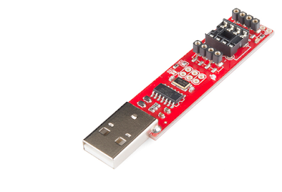
  • You can get an all in one programmer for about $16 USD complete with handy built in blinking LED.  But watch out for this gotcha....this one drove my crazy....on Linux or mac programming code into an ATTINY works OK. Then suddenly quits. Like you unplugged the programming board...but you didn't. Why? Turns out to be a USB permissions issue. To fix follow the instructions in this link or just do this : open your terminal and run lsusb from terminal. Then chmod the crap out of the usb ports with this: sudo chmod 666 /dev/bus/usb/0xx/0yy where xx and yy are the device ID's used for the ATTINY programmer.  You can make that change permanent by following the advise here.  Otherwise the "write to chip" commands in Arduino IDE become caloric; i.e., they donut work.


The AVRTINY programmer.  $16USD!!!


And now....Cons:

Biggest issue, con number one! There is no easy way to debug these damn ATTINY rascals.

What does this mean?

On the Nano, you use serial print commands for this, to see if a variable is working the way you want, for example:


void setup()
{
  Serial.begin(9600);
}
x = 100; // or whatever other bozo value you are trying to determine

Serial.println(x);
delay(2000);


If you expect to see a 100 here and get 0 in your serial monitor, that tells you you screwed up your code!

On the ATTINY, this debugging methodology is not so easy. That's because serial commands are not supported by default at all!

The workaround: There are lots of fixes for this. After digging I found a nifty add-in library called TinyDebugSerial. I liked it because it was easy to implement. And if you read this blog at all you know I like easy.

You can get the add-in here.

Drag the files into your Arduino library folder, then try this as code:


 #include <TinyDebugSerial.h>

void setup() {           
 #include <>TinyDebugSerial mySerial = TinyDebugSerial();
mySerial.begin(9600);

}

void loop() {
mySerial.println("hello world!");
}

OK, serial print data, streaming at 9600 baud, now shoots out ATTINY85's "pin PB4" (that's pin 2 for those of us in the DIP8 real world). In this case "hello world" over and over.

But....Where to hook up the TX out? So you can read it, Elmo??

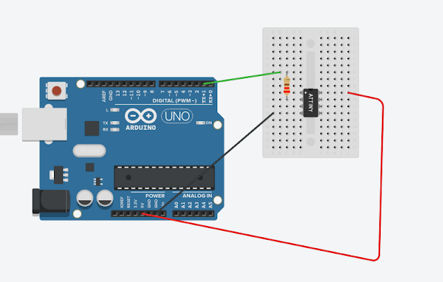
I ran it to a RX pin of an Ardino UNO via a 220 ohm resistor--hooked the UNO up to a 2nd USB port in my Linux laptop--fired up a new IDE window for the UNO--set the USB port in the IDE for the uno--and (finally) read the serial strings out of there. Worked!

Using an UNO to get tinydebugserial output from an ATTINY.  Wire it like this....

Con #2:
there just aren't that many pins to work with. This is an 8 pin chip and 2 of them are for power.  1 more is for reset, and it can do other things, but not easily. Not much more to say there. Sorry.

Con #3: the pinout designations are odd for ATTINY.  I found for analog in I had to use something like "A0", "A1" etc. For digital I had to use "3". I had to check the pinout diagrams online more than a few times, and for me, screw around a bit....

For instance, analog Pin A2 is tied to physical pin 3 and A3 is tied to physical pin 2.  But why, Scottie, why?


Con #4: ATTINYS are slow, slow, slow, SLLLOWWW and then they are slower than snot!

Overall--I almost gave up a few times--really, for audio DIY why use ATTINY at all and not just a Nano? Or Uno? Or Due? Or  Dookay?

Not sure I can answer that....but then I came back to it...I bought the damn tiny things--I just have to figure it out.

After a few evenings I did get it working, and with debugging set up could start to do useful things. So yes there are probably more cons than pros. I programmed it anyway. Guess it's just the way I am.
Doesn't mean you have to be that same way.

Soon to come--using interrupts to track CV gates with these little turds.  Until then.....well you  know.

Friday, November 9, 2018

Reverselandfill PCB Swaps and the Crazy C1406HA Attenuator Chip. Thoughts about the old days.

History Lesson....

How it was back in the 80's: I'd get in my Station Wagon (or later, in a van, or a plane), get to the seedy club, and if the vibe was good, swap conversation, drinks, and, well, other things, with my new found friends.

If said friend was a fan, tour caterer, flight attendant, promoter's daughter, and/or exotic dancer and liked wire-thin synth and backup vocal dudes with Brian May hair, (a few did, most of them liked the drummer better) try even harder to swap....well, you can guess right?

This was the 80's and I'm oversharing....so let's fast forward 30 years.

My Brian May hair and Ford Country Squire are long gone. I don't drive to clubs a lot nowadays; instead I get up early and control/alt/delete a PC.....mess with Eagle and whatever audio PCB I am trying to finish, look at audio websites and peruse PDF data sheets extolling obsolete OTA IC's.

Feeling social? Not often, but if so, perhaps I will email like minded audio folks, many of whom live halfway around the world. And if the vibe is good, we swap....

(.....wait for it?)

.....printed circuit boards!!!

(Welcome to my World.)

One such swap occurred recently with Electro-Music mensch Martijn Verhallen from reverselandfill.

Martijn and his site are chock full of creative ideas and music. To name a few: he does crazy things with video synthesis; mounts synthesizer PCBs on slabs of wood, and produces noise/dark electronic/soundscape  music.

I sent Martijn a couple of Lunetta VCO variation PCB's as well as an ASMVCO.  In trade he airmailed his "Aconitum Noise Mixer" PCB along with a CMOS based noise PCB with on-board patching called "Noise! Oscillator".

I have slim to no white/pink noise capabilities in my homemade synth so let's build the Aconitum first.

ReverseLandfill's Aconitum Noise PCB

Aconitum combines a few analog staples--the "get noise out of 2 pins of a gained up transistor" and the "two inverting op amps in series mixer"--along with active filtering--a bunch of pots and jacks--into a small board.

I could build this box stock, which would be fun, but it's even more fun to mod it.

How about adding CV control of the noise levels? Why not?

There are a hundred ways to do that, an easy way: use VCA's. I have already messed around with that--the Farm VCA and Irwin VCA for instance. But, as per my initial push into DIY, I want to see if I can do something new (for me anyway). Let's try using a chip that you may have never heard of. I know I hadn't!

It's called the C1406HA:


 As far as I can tell, the audio consumer mass market was the C1406HA's target. Fair bet whoever designed this IC never thought it'd end up in a synth.

I say SIP it!  SIP it good!

The C1406HA a voltage controlled stereo attenuator.  OK, the 1406 might useful for what we do, but buying these IC's was a shot in the dark--I was putting together an order for Goldmine (switches and caps) and saw this, on a lark I bought ten of them--they cost pennies--figuring, if they didn't work, toss em.


I bread boarded my first C1406HA and--viola! they are super simple and work great! The CV to audio curve, to my ears, is very musical; the distortion is there but not too bad, certainly acceptable for mixing noise and grunge.

Proof of Concept for 1406 was 5 parts--the chip and 4 caps!

If there is any issue at all with the C1406HA it's that its channel separation is butt--the spec sheet says 60db but really I doubt that, to me it sounds a lot worse, but for attenuating noise signals, who cares? Maybe the crappy channel sep makes the thing sound better?

I spent an evening creating an Eagle "experimenters board", which I will get fab'd soon. It will (if it works?) accommodate two 1406 chips, which allow control of 4 audio signals.


 C1406HA Experimenters Board.

In  case you're curious: where can you buy this chip? As far as I can tell was been discontinued during the Eisenhower administration (a bit after, but close?)  Goldmine no longer has them.  Damn!  I found more in China at affordable prices--UTSOURCE in China, had them for 50 cents each USD and $4 for postage.  I have no idea if they will ever show up, much less work. But DIY is about gambling--both money and time? 


UPDATE! The UTSOURCE chips showed up and appear to be just fine. The PCB I created for the C1406's works but has a lot of errors. Read Part II of this build, where the module is finished and Doris gets her oats here. Until then, don't breathe the fumes.

Monday, November 5, 2018

SMALL B.O.W.A.L: Creating DC Bias Offsets with a Control Voltage

Last time I was extolling the virtues of creating DC offsets for control voltage and audio signals.  This can add color to LFO signals, wave shapers, modulators, and other devices.

To review, what does this mean?

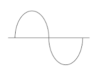
It means you start with an AC signal like this:

Figure 1: standard Sine Wave
And you offset it a few volts above ground so it looks like this:


Figure 2: sine wave with DC bias offset

The B.O.W.A.L. circuit from last time let you tweak the bias with a potentiometer.

But! Wouldn't it be nice to be able to do the same with a control voltage?

Turns out it's not hard.  We start with the same PCB:


Then add some wiring instructions which you can find here. And yes I realize that the PDF is hard to follow (crappy handwriting).  Hopefully this next diagram helps--it summarizes the 4 main wiring mods you need to add to hook the op amp stages together to make this work.


Wire all that up and you have 2 fully independent, buffered bias offset circuits; feed in CV and out comes the input sound or another CV, offset by the amount of CV at the "bias" input.  Easy!

Some bench photos. Means not much to anyone but me, but it makes me remember the zen times at the bench putting this module together. That's the good thing about being a blogger--as long as you're not overly offensive, you can post any damn thing you want.

Like Big B.O.W.A.L., Small B.O.W.A.L. worked the first time without kludges, tweaks, and changes. Two in a row.  I am trying to stay humble.

The wires here turn four channel BOWAL into two channel Small Bowal

Skiff?  We don't need no stinking skiff!


B.O.W.A.L. brothers....


Bench B.O.W.A.L.


Still with me?

Interesting synthesizer patches may be imminent when using CV to offset an audio or control voltage....a lot of times you want to get rid of DC offsets, but not always. Hear what Small B.O.W.A.L. sounds like here.  As usual, no effects, tweaks, tricks etc. for this demo.  This is all bias offsets using the circuit in this post.

details about the demo:

00:02 CLASSIC MOD F/X
  • Slow LFO goes to Small bowal input.
  • Small bowal CV input source (for bias offset) is from an AR
  • AR is set to immediate attack and moderate release.
  • Post-gate LFO climbs down from an offset of about 3V above ground to zero volts. 
  • Sent this offset LFO CV signal to a mod input of a VCO.  VCO set to ramp wave  
  • So you hear the warbly mod pitch descending as the CV offset goes from around 3V to 0V.
  • This is a popular mod trick for modular synthesis. A bit tired perhaps.

00:20 Distortion unit becomes waveshaper
  •  Sine wave to small bowel audio input.
  • DC offset of this sine wave with slow LFO, maybe 1V P/P
  • Feed this signal into input (1) of the SON OF ZENER
  • The other channel (2) of son of Zener is a triangle wave.
  • You end up with something that sounds a lot like a Serge Waveshaper meets VCA.  I have no idea why.

00:55:  Goose a Korg MS20 style ring modulator 
  • 1K Ramp wave > Small Bowal input.
  • Small bowal CV input is modulated by ADSR.  
  • So ramp wave is starting with a  DC offset and falling back to 0V
  • That's fed into X input of the ring-mod.
  • Y input of Korg Rmod is ramp wave, unadulterated
  • You end up with the ringmod effect that is not audible, then suddenly very audible.

1:21: Odd things happen when you DC offset audio into a balanced modulator.
  • Not everything will sound good here, you have to mess around.
  • pulse wave (audio) offset by SB. 
  • SB bias offset modulated by slow LFO. 
  • SB audio output to Y of 3080 or equivalent balanced mod. 
  • X in to B-M is another pulse wave. 
  • Balanced mod out to VCF > VCA
  • You can get all sorts of very odd sounds from this.  If you have a balanced modulator, without AC coupled inputs, try messing with putting DC audio offsets to feed X & Y inputs.

OK next up I have some guest circuits from reverselandfill.org.  Stay tuned!

Anything to Clock Subcircuit

Readers:  If you want to build the project featured in today's post, please go to  PCBWAY's  Community pages --a gerber ready to dow...