Friday, April 28, 2023

Bench Mixer--Looks Matter

Existential Question: Is AudioDiWHY a dating site?  Swipe left, swipe right?  

Use Arduino to automate the swiping?  

Unlikely, but--maybe.

I have brought DiWHY modules to my geeky audio meetups that sound great (well, I think so anyway) but are --fugly

The guys roll their eyes. 

Then I bring in something pretty boring with a neat front panel and layout and they say--dude--cool.

Swipe right?

The bench mixer discussed in today's post exemplifies the latter--doesn't do a whole lot, but looks good, enough to get the coffee date, maybe more, I think.

You can read about the first attempt at the layout and what I was trying to accomplish (no not that!)--post is here. I went too fast, got cocky, and made lots of mistakes. Sound familiar?  

Fixed it this time, it works, although the L > R callout is backwards on the front panel. Red flag? Deal Breaker? Nope. That's fixed in the gerber I uploaded to the PCBWAY community page for the project. 

Ah yes, PCBWAY.  Shout out to Wendy! Help out this blog and check 'em out.  In fact, please!! click this link to PCBWAY and help this blog out--it will register in their analytics that you read this blog; their community home is here.

OK, Let's look at the butt ugly swipe left frac module this date-worthy mixer replaces:

But...but..your profile says 5'-10"!!!

Here's the new one again:

"AudioDIWHY-- No Catfishing"

This is a simple bench mixer--audio at input (2 x 2 with normals to handle mono audio) is mixed to 2 screw terminals in the back, which in turn gets connected to a power amp and speakers. 

Two op amps, some hardware, dual concentric pots, and a handful of resistors. Dumb! Easy! That's what she said....

Happiness is new boards from PCBWAY!


On to some useless build photos:

Soldered in the SOIC op amps.  Not too hard to solder, no microscope needed.


Test fit....we'll know more after the 4th date.

What is it you do for a living?  You're a tech right? 

"A rule--I don't date geeks".....but...wait....you're gainfully employed?

Not shown in the photos, but it's there: be sure to connect ground on the main board to ground on the jacks board. You can use a 2x 100mil male/female jumper; to get this done fast I soldered 22 gauge single strand hookup wire between the boards.

If you want to take this one home, I posted gerbers, PDFs, Eagle files, BOM, etc. for this module on PCBWAY's Project page--here

If you build one you will need 3 PCBs: the jacks board, the board with the op amps, and the front panel. 

For the front panel I'd recommend black solder mask with white silk; check the box that says for an extra $1.50 don't put the order # on the PCB.  Something like that. 

Enjoy the swipe right look.

That's it for this one--above all, don't date the fumes. See ya next time.

Saturday, April 15, 2023

Dual MS20 Euro Filter--Finished! Works.

Joy! I took a Rene Schmitz MS20 filter schematic you find everywhere and turned it into a compact MS20 filter board--post on that board is here (PCBWAY community page--same PCB--is here).

This time I turned two of these with 2 additional PCB's into a dual Korg MS20 filter clone--a 15HP Eurorack skiff-style synthesizer module. 

You can download files for this project from the PCBWAY Community: Pots and jacks and front panel and MS20 VCF board.  Again, get the gerber for the VCF board itself here.

So you'll need 4 PCBs to build this module.... 

I spent a lot of time making sure all my measurements were correct, which was a pain, but it's a bigger pain to deal with things that don't fit.....

I have the module in my rack and am happy with how it came out (although not 100% happy, see "improvements" section below).  You can get all the cool distorted Daft Punk distortion stuff, MS20 bandpass madness, fat basses, the whole thing. 

Here are the bench photos. Of questionable use, but, I take them anyway.....

Layouts done, schematics checked; gerbers sent to the blog's trusty sponsor, PCBWAY--they're back!

Project uses 4 PCBs: a front panel, pots n' jacks board, and 2x MS20 filter PCB found here.

From here it was like building a kit....which happily, in this case, worked!

Hardware! Check the BOM here for what's needed.

For the filters, make sure to solder in the SOIC op amps first....

.....then solder the other parts.


If this is your first Euro skiff build: make sure to place the hardware into the pots and jacks board but don't solder anything yet. Place the front panel onto the jacks panel, and once everything is in place and lined up, flip it over and solder:


With all 4 boards assembled I tested them:


Ah! Worked first time! Smells Like MS20 Spirit to me....


The audio inputs are normalled together, as is CV1-2 to CV2-1. Another option would be to normal filter out 1 to filter in 2, but that's easily done with a short patch cord.  It could be on a switch? Maybe in a future revision.

Overall in its current form the module sounds great....once again, if you want to build one of these, you can get the front panel and jacks/pots gerbers from the PCBWAY community page here and the filter boards here.  I suggest asking them to fab up the front panel in black with white silks; make sure to add a comment when you order that you want the order number on the rear solder mask or click the "For an extra $1.50 don't put an order number on the PCB" checkbox when ordering.  I forgot to do that and you can see a small order number to the right of the "Peak" knob.

IMPROVEMENTS

Now that it's in my rack I can see changes I'd like to make:

  • The 2nd output of 2nd VCF should be a mix of outputs of both. Easy--single TL072 mixer, add this to pots n' jacks board
  • Would make more sense for the normal to be from audio out VCF1 to audio In VCF2 (or maybe switch between normal from out1 and in1)?
  • For 5V CV systems, current limiting resistor at CV input of each VCF PCB should be a lower value. I have a 5V system for the most part, so I need to take the filter apart again to change these values, but am too lazy.
  • For the frequency control for each VCF, add resistors between the 100K pot and +/- Voltages.  This would get rid of "dead spots" in the filters' overall frequency range. Add this to pots n jacks board.
  • From bench experiments, it should be possible to increase or further punish the audio signal in feedback loop of each filter, creating a "super Daft Punk" MS20 filter. In the BOM I mention using an A50K instead of A100K for peak, which leads to truly crazy distortion, but also some odd behavior at certain frequencies. Update: still working on this "distortion plus" design. Seems 50K pot alone won't do it. Stay tuned....

All of these except the distortion redesign are easy fixes, but I am not sure I have time....Someone? Anyone?

OUTTRO

On to new things....I went to an ARP2600 focused geeky meetup the other day and was impressed with the simplicity and utility of its voltage processors so I may work cloning them next.

So! Until next time--make MiStakes, experiment, have fun, and blow things up--beakers are cheap. Happy subtracting.

Sunday, April 2, 2023

Bench Mixer: Stupid Mistackes

Back in analog-land: time to replace a Frac bench panel with something more high class.

Panel on the left passively converts 3.5mm jacks to 22-ish gauge binding posts connected to a power amp. Top notch aethetics, right?

The old board, built from a frac aluminum panel, worked, but was butt-ugly.

Let's redo this in Euro

I figured I might as well throw in a mixer while I'm at it. 

Easy right? This is a couple of non-inverting op amp mixers. I can lay this out in my sleep! It will work first time!

Nope.


The idea: have independent mixing for left and right outputs with some normals to handle mono inputs:


Bing, bam, boom! Designed in Eagle....created gerbers....got the boards back pronto from this blog's patient and highly enthusiastic sponsor, PCBWAY:


Happiness is new boards from PCBWAY! Please help this blog and check 'em out.

The project was centered around dual contentric pots (you can get these from small bear and other DIY vendors), but I could only find these in 90 degree variations, not 180 degrees. So, not a slam dunk for Euro skiff, which has to not exceed about 30mm in depth. 

I might try to lay out a skiff-friendly adapter for these handy dual concentric pots, but this time I ended up side-mounting the PCB:


Once ready to test I used two "con-244" 100mil connectors from All Electronics, soldered back to back, to connect the jacks PCB to the mixer PCB:

Why is it not fully soldered? D'oh! Keep reading....

When ready to test the module looked good!


One big problem--it didn't work!

At first literally nothing; no audio at output. I hate this! But why scotty why? Turns out, the pots were wired upside down! So CCW rotation turned the volume all the way up. CW turned it all the way down. Very nice.

What's wrong with this picture? 

(HONK!) For volume to go up when you turn the knob up, the arrows have to go up!  

There is another problem here.  See that "in 2"?  It needs to be connected to the right channel so L1 and R1 come out of the correct output! Missed that too.


More issues! The drills for the output wire blocks were too small!  Easily fixed? Just jam 'em in there anyway and solder, right? Nope. I tried that, and what you see here "worked", sort of, but, felt flimsy and probably would have failed eventually.


It got worse! I forgot to wire ground from the main board to the jacks board.  "Who needs ground"?


Nice kludge wire for ground

Also the L1, R1, L2, R2 wires from jacks to main board were out of order. I tried cutting and rewiring the 4 conductor jumper but about halfway through I realized: too many stoopid mistackes, too many kludges, shut up n' redesign the damn PCBs.

Overall this was a huge fail. I thought this was going to be an easy build and rattled off the design with way too little forethought.  

What now?

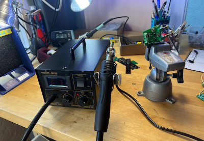
The grim reaper of DiWHY?--sparkfun air work station

Get out the hot air! I removed any parts I figured I could reuse on the next iteration; the PCB goes into ewaste:


...and then redrew the boards to fix the mistakes.

Improved jacks board with a ground!

So back to PCBWAY for another go around.  

Time wasted: two evenings.

I'll keep you posted.  Until then, don't breathe the fumes.  Update: rev 2 works!  Post is here.

Anything to Clock Subcircuit

Readers:  If you want to build the project featured in today's post, please go to  PCBWAY's  Community pages --a gerber ready to dow...