Friday, August 31, 2018

Arduino based SYNTHDVM--Up and Running.

Hello again, yes it all works.

The SynthDVM is as far along as I think i will take it.

For anyone who wants to catch up:

Part one is here--as I try to master the art of undocumented Arduino clones and parts.

Part 2 is here--Design goals for the project.

Part 3 is here--Let's get the OLED meter to look "analog"


Part 4 is here--  clobber that op amp!

About the DVM, It reads DC from about -10.5 to +10.5V with an accuracy of better than 1% throughout its entire sweep--very close to .5% for say 5V and pretty much dead on between +/- 3V.  As they say (I say)  in audio DIYland "good enough".

If I designed a custom PCB for this, which I see little point in doing, with a good layout and large ground plane, it'd probably perform better but it's not bad for a sandbox PCB, a nano, and a handful of op amps.

There were some evenings of cursing over this one, I had some ripple on the op amp + and - rails I couldn't get rid of, but I finally re soldered a few traces here and there and now it's fine.


I haven't got the artwork for front panel done yet, but that's coming soon I hope. The front panel is completely simple: the left jack is input; the right is signal thru. The switch chooses between AC and DC at input.

Yep, I decided that I wanted to measure the amplitude of audio signals as well as CV DC. To get that done I used an AD736 RMS converter chip, which is so easy to put into your projects it's almost funny.

I copied the AC to DC design I used in the DVM straight out of their app sheet (page 13).  Yow.  The switch hits a digital pin on the Arduino and tells the arduino to read the output of the AD736 vs. the op amps that are running DC. Simple!

More features?  It's software, why not? If anyone wants to take this over, it'd be cool to have the switch throw an interrupt (or whatever) and redraw the needle graphic as a VU meter, since the RMS will never read a negative voltage, but I am tired of working on this one and need to move on.


From the build...I built up the DC part, tested it working, then bread boarded the AC-RMS sub-circuit on the trusty Radioshack learning  lab (circa 1977--still works great--and I didn't know this but you can still get them!).  After I got that working--easy--I moved all the parts to the circuit.


I used the PCB you can read about on my website for all the op amps, the Nano 10V regulator, as well as the Arduino Nano itself.  Also if you are thinking of building this or something like it, please take a look at the schematic and build notes PDF. You can review the code on Github and I'd also suggest looking at my last post about this to read up on a cool "clobber the op amp" trick which I think is useful outside of just Arduinoland.


What next for cslammy and Arduinos?  Who knows?  Until then don't breathe the fumes!

Friday, August 24, 2018

Synth DVM part IV: Neat Arduino Trick--good for Audio DIY--Crush that op amp!

I finished (!!) my arduino based Synth DVM, it worked last night anyway; need to do a few final software tweaks then will post.  As always I am sure someone can improve it, but it's working well.

You can see part 1 here--I try to master the art of undocumented Arduino clones and parts

Part 2 is here.  Design goals for the project, Blah blah ginger blah blah.

Part 3 is here.  Let's get the OLED meter to look "analog"

How it looked about a week ago...front panel an "alubase PCB" from PCBWay....the PCB is already bolted on. Along the way I found a cool and easy way to make an Arduino treat audio like it's running through 4066 cmos switcher. Maybe better?

It's a nifty enough trick that I thought it should have its own post.


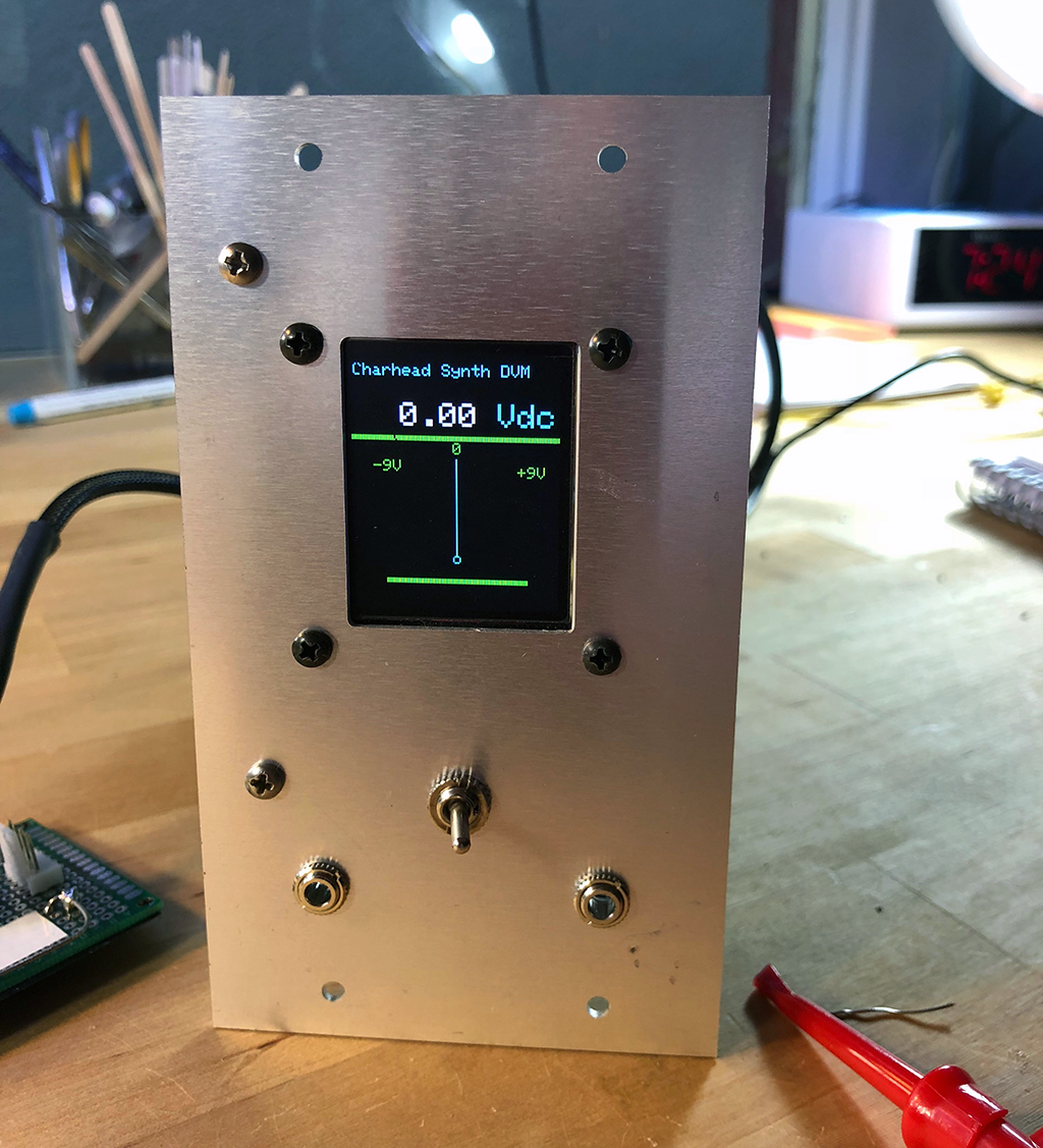
My DVM.  FracRack panel.  It's actually done and working now.../


The hack goes like this:

If you've screwed around with Arduino for more than a few minutes you find the things don't like negative voltages w high current on their analog pinssince my SynthDVM is chock a block with negative voltages--it needs to read negative voltages relative to ground, I had to deal with this.  OK....

As long as you're careful with your design, carefully incoming limit current, we're fine, there's diode protection in the Arduino analog pins, but what if we're not fine?

Just to be safe, negative voltages at analog pins should be designed out if possible?

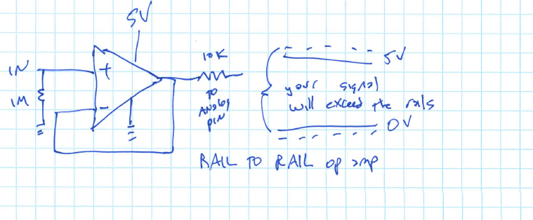
There are many ways: use an op amp in front and use GND for V-- and 5V for V++


But this will chop off some of the upper voltages close to 5V and voltages near Ground.  Not good for a DVM!

Or block the negative voltages/reverse bias current using a diode....


You'd still have to figure out a way to limit the upper voltage since Arduino pins don't like to see more than 5V relative to ground, maybe use a zener for that?  

But for a DVM this is a non starter--the output voltage sees a "diode drop" of .6-.7V which for a DVM application probably isn't good--we want incoming signals to be as unadulterated as we can. And diodes are temperature sensitive....

How about a rail to rail op amp?  I probably could have made this work, but I fried my last R-R op amp on the bench working on another project--oh well. There is also the consideration that many R-R op amps allow signals over that can go above the VDD, but I figure Arduino can probably roll with that.  

Thinking about this project, I should have just bought more rail to rail op amps--yep I should have dug into this idea more.  It probably would have simplified the design a lot. Something for a future post.


AC couple and then do an DC offset?  That would have limited my measurable signals to something like +/- 7V by my calculations, and from +/- 15V supply I wanted to be able to measure more like +/- 12V.

There are lots of ways other ways....

I discovered a way to do this by accident: you can use Arduino digital pins to clobber an analog signal, negative or positive, as long as it is less than say 30mA (as I read the Atmel datasheet, it's 40mA, but let's stay far away from that....)

So how about this hack:


You still have to protect things to not go over 5V--I used a voltage divider as you see here, which for me worked fine but if you're really concerned, perhaps use a zener to limit the top end to 5V.

For an inverting op amp, it's the same idea--connect the output pin to a digital pin on the arduino and suck the signal out of the op amp to ground.  I think I did this something like this, I will post the final schematic soon:


R1 limits current to D3, so that's important (!) and R3 limits current through the op amp--so be careful with these values.

Now program your arduino like this:

      pinMode(3,OUTPUT);
      digitalWrite(3,LOW); // PIN3 is now a working ground. Send a signal destined to go to A0 to ground; so we clobber analog signal to A0

(or)

      pinMode(3, INPUT) 

D3 goes high Z, op amp unaffected; signal delivered to A0 just fine.


So that means that you can use this trick to turn on and off analog signals as you would (say) a 4066 or 4016 cmos switcher. Output/Low the signal is off.  INPUT, the signal is on.  Easy!!!!

Cool! I didn't think it'd work but it did! 

Questions:
  • Do I think I made this hack up?  Nope. If there isn't documentation about this hack somewhere else already, I'd fall off my chair, but for the 2 cents it's worth I couldn't figure out a way to google it. Whatever. 
  • Can I flip/flop pinModes every x milliseconds and not screw stuff up?  Yes. It seems to me like flip-flopping pinModes very quickly--input to output--and back--doesn't phase the ardino at all. This surprised me, but for my design here, nope it wasn't an issue. I haven't totally tested this vs. say a 4066 for "what can flip faster?  What "sounds better?"  Don't know. Put it on your bench, fool with it, and let me know!
  • Does this work for clobbering audio signals that are more than say 2.5V P/P?  Yes. I could power my op amps from +/- 15V supply, run an audio signal to close to the op amp rails, and still use the above hack to clobber the signal.  Just make sure you are careful about resistors like R1 and R3 in the inverting diagram above.  We don't want to send too much current to the OUTPUT/LOW pin, or the A0 analog pin, and we don't want to heat up the op amp but not limit its output either.  But as long as you can work with that, we're good.
  • Does it work for positive or negative V relative to ground?  So will D3 in output-LOW mode source and sink current? In rapid succession? Yes.
  • In this application, does this work better in this app than a CMOS switch (4066?) for me, yes. 4066s just don't work well with voltages below Edison ground. There were other ways to do this, for sure, but this worked.
OK More on the entire DVM project soon, I am pretty much done, just need to finish the documentation. I am pretty happy with how it came out....and that I stumbled into this OUTPUT/LOW INPUT hack along the way!  OK enough until next time: don't breathe the fumes!


Thursday, August 2, 2018

40106 Quad opto coupled VCO--Lunetta Lives!

All hail Lunetta Synthesis--the CMOS anything-goes way of thinking about Audio DIY?


One thing that appeals: Stanley Lunetta is from the California Central Valley, same as me--from my reading his studio was about 40 miles from where I was recording back in the day.

Does this prove that we Central CA folks aren't all farmers and politicians?  Does it need to be proven? Growing up I remember a great music scene, at least in the 70s. Makes sense--there was very little else (legal) to do!

OK: In honor of Lunetta Synthesis and all Central Valley artists I decided to fab a quad VCO using one of the great CMOS chips, the 40106.

I've messed with this chip before but this was my first attempt at doing something this, well, VCOish.

I went through a few generations of experimenter boards by designing in Eagle, and sending off to EASYEDA for a test fab.  I almost have given up on perf'ing things. It's faster and easier for me to have boards fab'd abroad, sent back to the US, and if they don't work, try to kludge them into operation or just toss them and start over.

OK, the board I ended up using for this is here (on my website) and tests working.  Yeh!


Here's the schematic....you can get a zip of this in Eagle format on my site.


Ok so what is up with R1, R2, R3, R4?  You can use the values in the schemo above and call it a day, but what fun would that be? Instead I replaced these resistors with optos: four optocouplers bought surplus from Electronics Goldmine, but for this design go ahead (!!) and use whatever vactrol or pot or resistor or thingy you care to use. Or just use a resistor? Try different things. See what you like. Experimentation is the key here, have fun!!!!

Using the optos, I could get pretty decent (but highly non-linear) output from LFOish, maybe 2hz? to about 12K and up.  Good enough for F/X.

EZ buffer circuit fragment used for the optos

One thing to keep in mind: the 40106 is a lot of audio for the buck but in reality can't hold a pitch to save its life. Any temperature or current variation--even a slight one--drives the output pitch crazy. Even power cycling the chip can change its pitch for a given RC value. So it's no substitute for say an ASM VCO.  But for effects and noisemaking, it's just fine.

About the goz-outtas: This is a bit un-Lunetta but I wanted to get the output waveforms 10V P/P or close. So I also incorporated some quad TL072 based buffer boards I have been messing with for a few months. I will try to post more details on my website soon but this is four of the non inverting op amp gain stages you can find on my website fab'd on one PCB.  

I had to go through a few generations for this--the first gen had a bozo mistake with how I laid out the resistors, but what is below worked.  I have already designed Gen3 with a more logical layout for the resistors which are all over the place in GEN2.  this is the world of easy PCB prototyping?

This is basic op amp stuff, but the quad non-inverting board can be used to take four different CMOS type signals and turn them into say +8V Peak to Peak with a 4V DC bias offset.  Since you have to buffer the triangle out of the 40106 I had to do something like this right?


UPDATE.  It makes more sense power supply wise to use inverting stages w bias offset vs. what I have below. The boards will draw much less current!  I have information about a more power efficient board in the BOWAL project and on my website--if I built this again I'd use the buffer/bias circuit here.

"It even does FM": Another interesting thing: it's way easy to add FM to this. Add a diode reverse biased and a 1K resistor in series ahead of the RC that sets pitch and then feed it any audio signal above maybe 2V P/P for um.....interesting results.  I will try to post some bleep-bleep sounds but for me this is hours of fun.

In other words: take this fragment and put it between your audio signal and the FM1, FM2, FM3 etc. inputs you see on the board.  Does it get easier?


Some build photos......

Finished module, still need to do front panel artwork.  

Perfland, easy way to make a few small boards into one big module
OK time tor record.....in case anyone wants to see more here is a zip of the entire design pdf.  if anyone has other ideas about this please comment, I'm always up for seeing what others are doing in 40106 land.  And I will try to add sound samples down the road.  Don't breathe the fumes!

Anything to Clock Subcircuit

Readers:  If you want to build the project featured in today's post, please go to  PCBWAY's  Community pages --a gerber ready to dow...