Hats off to this blog's sponsor, PCBWAY....check out their Community Page--clicking those links lets 'em know I have readers, which helps me create new projects. Thanks!
==========
This time I continue to clone or knock off subcircuits from the legendary ARP 2600 synthesizer. From my patient sponsor PCBWAY I recently received an ARP 2600 inspired synthesizer preamp PCB I laid out. Let's see if my design works or is butt.
But first, here's an incredible (?) piece of luck....I was walking around my neighborhood the other day and in a sidewalk box bursting with "Covid Pandemic--Free Stuff!" discards found an almost new-in-box Radioshack/Realistic dynamic microphone circa 1970 or so:
 |
| USD $9.95! Hi-Fi Response! 10K impedence! |
The box was a bit worn but the mic inside was perfect....being period correct and all, I will use that to test my preamp.
 |
| The mic terminates in a 1/4" plug; I used a 3.5mm cable adapter a DJ I worked with long ago gave me. Can't beat FREE. |
ARP's design is a single op amp stage with a 3 way switch to select x10, x100 or x1000 boost by choosing different resistors in its negative feedback loop.

I know (knew?) zlich about mic preamp design but digging around the Internet:using op amps for the gain stages was an easy way to go.
I figured the hardest thing was finding a "Range" 3 or 4 position toggle switch I liked. After a bit of thought I decided to have each output signal (x10, x100, x1000) have its own 3.5mm jack instead of using a switch. This took up more space but was simpler to lay out.
I also decided to provide a cap-coupled AC input and a DC input; the ARP is only capacitor coupled only. The DC input would be normaled to break the connection to the AC input if used.
Furthermore, I brought a x1 output to patch to use as a unity gain buffer.
You can get the original schematic for the ARP preamp here (go to page 11). It's a pretty simple single op amp design; ARP used a Teledyne 133901 op amp with some clever resistor switching to get different output levels.
I took a different (and I think, simpler) approach to ARP's; I used 4 op amp stages in series:
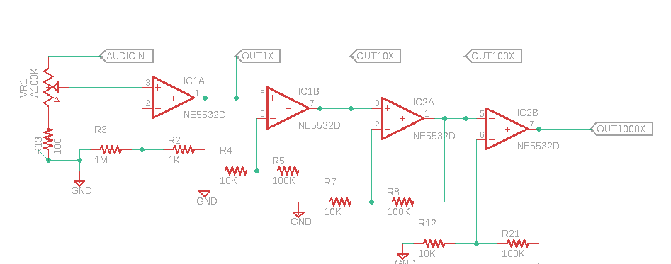
The rest is power and jacks...."keep it simple, stupid."
 |
| New boards from PCBWAY.... |

 |
| SOIC op amps were used to save space.... |

 |
| Ready to test.... |
 |
| I found that the .1uF filter caps for the op amps (not installed yet) were necessary to get rid of a bad buzz at the x100 and x1000 gain outputs. |
When I first powered up the board it acted strange--the 10x output seemed too "hot" and the 100x and 1000x outputs were slammed against V--.
After looking at this for a bit I realized I used the wrong values for R5, R8 and R21--specifically 1M instead of 100K, the extra zeros pushed the circuit into impossible amounts of gain--making the op amps do wacky things.
With the resistor values corrected the circuit worked and sounded OK, even with my big dude $9.95 70's era microphone. Not great--a lot of hiss and noise--but....OK.
 |
| I also made my first microphone for the project--a surplus dynamic mic element (Triad 1D1P 14R06C), cable tied into a plastic gum dispenser with some foam rubber shoved in for good measure. It worked, but sounded--well, crap. Maybe it sounds so bad it sounds good? Things can only get better! |
But--am I done? Nope. I was going to lay out a front panel, stick it in front of this PCB, put the gerbers etc. up on PCBWAY's project page, put it in my rack, and call it a day.
Then realized if I ever wanted to experiment with low noise design techniques, this is the project!
To that end: in the next few weeks, I will try different things--lower noise op amps, 2 sided ground pour, better power filtering, ferrite beads, etc., to see what if anything makes a difference.
 |
| Make me proud, son! |
Of course the freebee mic may be the source of some or a lot of the noise, but hey, I have other microphones.
Assuming the upgraded design sounds better than what I built today, I will upload that to PCBWAY's project page, post the schematic, include a BOM, and so on, the usual thing.
Until then, don't amplify the fumes!