Thursday, May 28, 2020

Vactrol Envelope Follower--From the Lab of Otto Wahh

I'm going back through my old designs from 2004-2005, laying out new PCBs, and rebuilding things.

Why = Whynot?

So let's build a Vactrol envelope follower I initially drew up when dinosaurs still roamed the earth:

A Poor Lazertran decal application detracts from the finished prototype--don't know what I was thinking with the bun n' weiner vertical graphic on the left side of the module. The front panel will have to redone.   

For the 2019 PCB, there is a serious trace issue with the + and - rails feeding the quad op amp.  Doh! I had to cut traces and add kludge wires.  This will be fixed in a newer version of the PCB.


What the VAC: In 2004 I had even less idea what I was doing then I do now, but I think the module came out OK; you can hear a sound clip of the module here. Pretty much everything you hear is processed in some way through this module, to create auto-wah, side chain effects, amplitudes creating  modulation via CV on a VST via an Expert Sleepers interface, and so on.

USING THE VAC-Envelope Follower:

The VAC-EF uses amplitude seen at input to generate a corresponding DC voltage at its output. If you've ever experimented with an auto-wah device such as a Mutron III or an optically based compressor/limiter you've used amplitude to voltage conversion circuits, a bit like this one, before.

Here's a typical application: change a bandpass filter's center frequency in response to the amplitude of an audio signal. Sounds like Jerry, right? Also: side chain effects: a drum track gets louder when another track is soft, for instance. Or: change phase when there is a loud passage for phase shifty sounds, crank up a distortion effect when the instrument you want to mangle is really loud, but not so much when it's soft, or for any of this, do the opposite.


BUILDING the VAC-EF: 

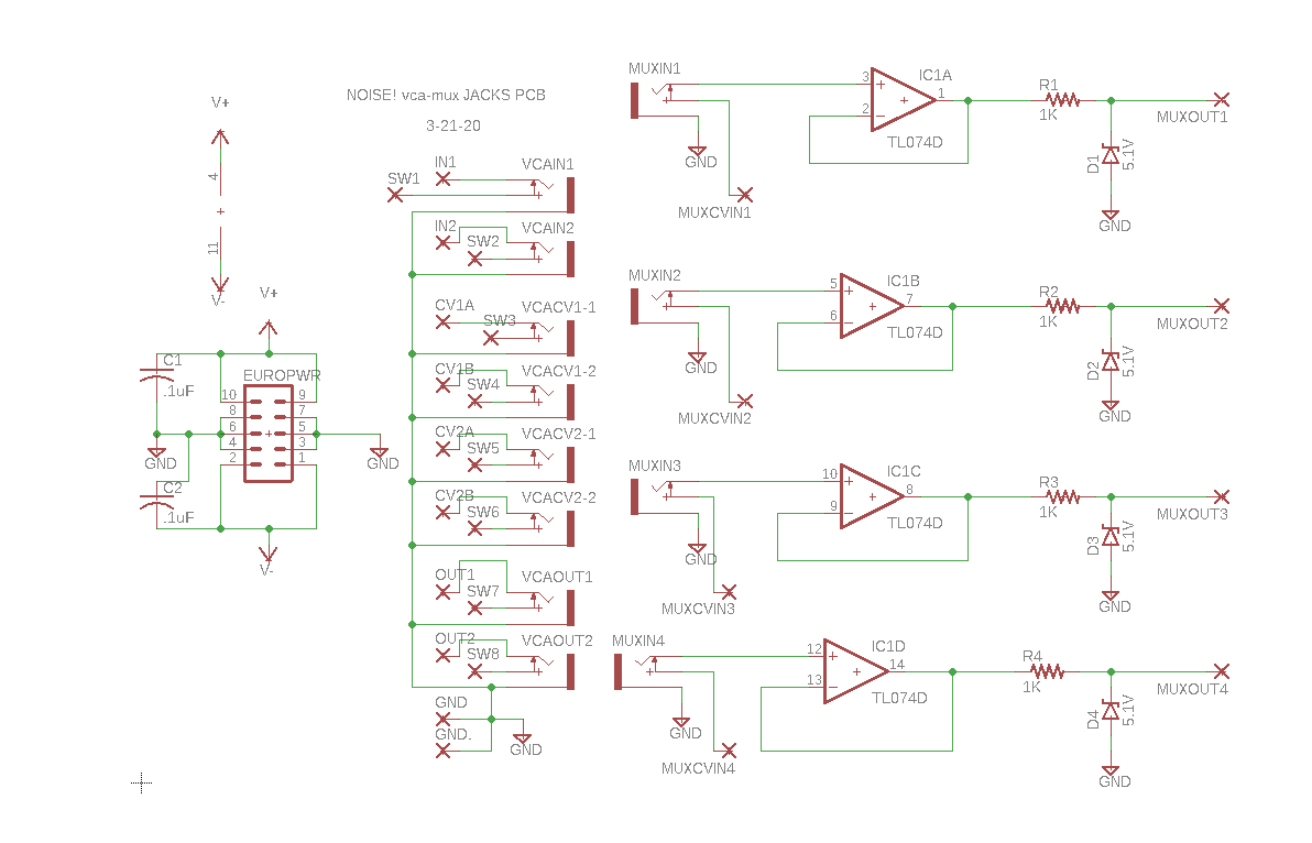
Here's the schematic from 2019:
I used audio taper pots for Sensitivity and Slope. R16 "Bias" pot is linear taper.


Board is designed to fit behind a 1u Frac panel:


Temp Front Panel!!! Does it surpass the weiner?

Overall the vactrol gives the module a slow, drunken, sloppy feel, which to my ears is (sometimes) a good thing.

But Why, Scotty, Why: I am not sure if the current source (a simple 7805L regulator) for the Vactrol is a smart design choice, but it works, I used this junk box part to supply current to the opto because I have a lot of 7805's in my junk box. How about putting the 2222 transistor in the feedback loop of the op amp ICB1? Is this a good idea? Not sure--I am not even sure it's necessary, but regardless,  I was experimenting and boosting the current in this matter gave the output a bit more "kick" so I kept this fragment in the design.

Overall, I've used this module  for the past 15 years and have been happy with its performance. The TL084 gets a bit hot sometimes depending on the module's settings which means the design could be improved; I'm not sure why it gets hot, but I'm too busy with other projects to fix it.

If you do build one of these, mess with R5 value to set the overall performance of the circuit. You might even consider putting a trimmer in series with R5.   

Here are some bench photos:


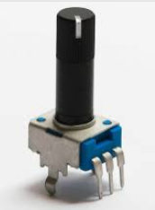
My initial test PCB used normal 9mm PCB pots and small knobs but as you can see the ergonomics were unacceptable. Hence I replaced them with tall trimmers which you can buy from Thonk:


FIXES: Again: if you build this module, it's important to note that what I have posted on my website has some mistakes in the layout. Specifically, I had to add 2 kludge wires since I screwed up the wiring for V+ and V- rails for the quad op amp. 

The Eagle files, PDFs including the fixes, etc. etc. are on my website, here.
  
For the 2020 board revision: I still need to test it further.  May do a dual VAC-Envelope follower in a 2u Frac?  A quad SMD version?  A version with 4 EF's, each with its own active bandpass filter? Who knows. 

Until then, have fun VAC-uuming, always suck at everything while you can, and above all (especially now right?  Stereo Pan-demic!) don't breathe the fumes!

Sunday, May 17, 2020

Noise! Lunetta Circuit Part IV: adding dual VCAs for Audio Gran-Turing-smos

Back again. I'm stuck at home with damn covid Shelter in Place and it's raining. Fortunately the PCB fab shop I use in China is still cranking and I got another set of boards for my Noise! Lunetta stack last week.

Built 'em up rawhide. Worked first time.  Here's all 6 PCBs to date.  The little switch on the left chooses the overall frequency range.

The project so far.....

About Noise!: It's an ongoing project I've been building for many months. I've tried to keep things organic: I think some damn thing, crank it out in Eagle, send it off, get it back, solder it up and see if and how it works. Like the Winchester Mystery House this project may never be completely finished.

It started when Martijn Verhallen from reverselandfill.org and I did a board swap. I really got into his Noise! tone generator and started adding to it, my goal being a full Lunetta type synth for oddball sound generation (I refuse to call this "Sound Design").

Part I--where I build up the base VCO and logic board is here.  Part II: resized and revised, here.  Part III: Adding a quad mux, here.  I created a quad digital pot board and added it to the stack, here.

AD5254 based quad digital pot board, Arduino controlled.  Post is here.

As I was messing with the interconnected PCBs: patching the stack to a bench VCA frequently came up as strange repeating patterns of audio bleeps and blurps. In the mod synth world this is not quite referred to as a "Turing machine"; as Turing modules I've messed with (a popular one has a demo vid here) produce CV, not audio, and on my bench it's the audio patterns that tend to repeat over and over. But whatever. Is a frequency to CV board coming next? Perhaps.

So why not add a couple of VCAs to the stack?  OK, easy, I already have built up a 2164 based dual VCA board (here), I just needed to lay it out again to fit the 3750x2000 mil footprint I am using for the project.

Got em back, built 'em up. No dumb mistakes--yeh baby. You can get eagle files, PDFs of schematics, Eagle files etc. here.

OK now the bench photos--sorry--some folks take photos of their dogs and cats, but I don't have dogs nor cats, so you get circuit boards.

The 3750x2000 dual VCA board.  

Ready to test....

The front facing board is a jacks PCB for the 3750x2000 dual VCA. While I was at it I added buffered CV inputs for the MUX board using the usual opamp/zener thing.


I used the usual super-low-parts-count zener clamp/buffer to keep the Arduino CV inputs from frying:


However I am curious about this clever fragment I lifted from a Mutable Instruments design--looks to me like it allows more stages with only one zener reference; didn't use it this time, will use it down the road.


After that, it became a matter of wiring it all up and testing.

Ready to test!


OK so how does it sound?  I still need to record the damn stack for real but you can see a vid of some of the repeating patterns at work here.

Is it for everyone?  Nope. Time to keep moving. Might do a powersupply and LFO and call it done.  I guess we'll see.  Until next time, don't breathe the fumes.

Monday, May 11, 2020

Transmitting 32 bit longs between Arduinos using I2C

No soldering this time--let's get on the bench and get going!

TINY BUBBLES

From a previous post, I've been messing with new old stock NSA1166 bubble displays for an upcoming audio project; Part I post about retro bubble displays is here.


The 70's era stuff is cool, but who wants to hook up a lot of wiring for the display?  I want to make these bubbles respond to I2C commands, as you might see in an OLED display like the one here.  

I2C has 2 wires to transmit, 3 if you include ground so not too much wiring. 

If you need to brush up on the I2C protocol read more here--or watch a really good video here--in short, it's a super easy way to move data between digital dookies.

This time I'll focus on one tid-bit:  I2C wants us to send bytes of data (8 bits) down the wire, one at a time, but for this project I need 24 bits on the slave side; since this 6 digit bubble can display 0-999999. How do we do that?

Wait--let's transmit 32 bits, since that will be a common need for other projects. So: my goal is to be able to enter a long value in decimal on the master Arduino and have it show up in decimal on the slave.

I set up a Proof of Concept on the bench to figure this out. 

An Arduino UNO was used as I2C master and ProMicro cheapo clone as I2C slave--the $2 USD ProMicro used D2 for SDA and D3 for SCL. You knew that right? I didn't. 

Read more about that here

The Arduino IDE gives us the extremely useful wire.h library right out of the box, greatly simplifying I2C programming so let's use that.

HARDWARE SETUP

Here's how I wired it up:

I couldn't find an Eagle device for a 20 pin Pro Micro anywhere so I created an eagle device (how-to for that is here)--it's the 20 pin ProMicro Eagle footprint you see in the schematic above.


BENCH PRESS 

I used 2 old laptops each with the Arduino IDE running and an iPad for web access. Probably overkill?

To get this going the I2Cscanner sketch (here) proved its worth again, I used that to make sure the I2C device (the ProMicro Slave) could be recognized before creating any new code.

The Uno R2 talked to a ProMicro using I2C. Wiring details can be found here.  Again: on the Pro Micro Clone D2 is used for SDA and D3 for SCL.


ROPE-A-SCOPE

Turned out my bang for the buck Siglent 1202X-E scope (8VA teardown videois here) can accurately analyze and show me I2C data, which i didn't know before doing this proof of concept. This feature proved invaluable as I debugged my crappy code--for Siglent users, check out the video on getting I2C analysis going: here. Wish I knew about this feature before....

A couple of reminders for myself: bytes, ints, and chars are not the same thing.  For the master code I could get sloppy with variable types, but not with the slave code. I'll have to think about that, but overall, for Arduino, bytes and chars are 8 bits; ints are 16 bits, and longs are 32 bits. Doh!   

Shut up and show us the code! 

The POC code sends a sample long value to slave 10000 times over I2C then quits, which should be enough to see if the damn thing is working!


///////////////////MASTER/////////////////////////
#include <Wire.h>


// next line, put any decimal # here 0 to 999999


unsigned long int longInt = 333456;  
//on arduino unsigned long goes to 4 billion something

unsigned char byteArray[4];
   
int c = 0;


void setup() {
// put your setup code here, to run once:
Wire.begin();
//Serial.begin(9600);
}


void loop() {


Wire.beginTransmission(0x4);

byteArray[0] = (int)((longInt >> 24) & 0xFF) ;
byteArray[1] = (int)((longInt >> 16) & 0xFF) ;
byteArray[2] = (int)((longInt >> 8) & 0XFF);
byteArray[3] = (int)((longInt & 0XFF));


for (c = 0; c < 10000; c++)
    {
    Wire.write(byteArray, 4);
    delay(10 );
//    Serial.println("Sending");
//    Serial.println(c);
Wire.endTransmission();
    }


}


///////////////////////////////////////
//////////////////SLAVE/////////////////////////


#include <Wire.h>

long value = 0;

byte byteArray[4];

byte x = 0;


void setup() {
  // put your setup code here, to run once:
Wire.begin(0x4);
Wire.onReceive(receiveEvent);
Serial.begin(9600);
}

void loop() {
  // put your main code here, to run repeatedly:
delay(100);    

}

void receiveEvent(byte)
{
  Serial.println("received");
  while(1 < Wire.available()) // loop through all but the last
  {
   
    for(int i=0; i<4; i++)
        {
         byteArray[i] = Wire.read();
        
     //    Serial.println(byteArray[i], HEX);
   
        }

  }
/////// convert back to long
delay(100);
for (int q = 0; q < 4; q++)
{
  value = (value << 8 ) + (byteArray[q] & 0xff);
}
Serial.println(value); 
}

BOARD YET?

I am also working on a PCB for the I2C slave arduino, bubble display, shift registers, pull up resistor array, etc., so far it looks like this; I might send it off for fab this week.


Enough! If anyone has questions about the code, bubbles, PCB, and all else, comment away, but for now, on the bench the POC works; putting a long value in the master code will make it show up in serial out on the slave side. Joy!  For the PCB, who knows--more bubble stuff coming up, as well as an audio chaos generator, just in time for the global chaos we are going through right now. Back to soldering soon. See ya.

UPDATE 7-18-20: Aloha! got this all working, see the Part III of this post here.

Anything to Clock Subcircuit

Readers:  If you want to build the project featured in today's post, please go to  PCBWAY's  Community pages --a gerber ready to dow...