Thursday, December 31, 2020

Analog Devices AD9833: Accurate, Fast Sine, Triangle and Square waves using Python

This is hopefully the last of the FTDI232H posts? Not many readers for these FTDI posts so far; guess over the holidays we have better things to do (not me?). 

Really, it's a pretty cool little board.... 


To wrap up we will use affordable breakout boards to make function generator accurate to 10Mhz+. To make this go, you will need an FTDI232H breakout board, Python 3.6+ and the PYFTDI module, and an AD9833 breakout board; the Bob's are available from Amazon, AliExpress, and all the other usual places. 

You may want to first read about getting started with the FTDI 232H breakout board in the last two posts, here and here.

I hate breadboarding so a small PCB for this project may come around one of these days?


I already got basic AD9833 SPI going at the end of the post here; this time I will flesh it out so you can edit values for the waveform and frequency directly in the Python code; out comes the waveform at the frequency specified on your scope--accurately.  

(Get the python code here from Github, but here is the 12-26-20 version:)

from pyftdi.spi import SpiController

############user changes these###############

user_freq = 1000

wave = 3 #1--sine   2--pulse  3--tri

##########################################


#pinout from H232 for SPI


'''

#WE WANT TO BE ABLE TO ENTER A FREQ TO SHOW ON SCOPE.

# Instantiate a SPI controller

# We need want to use A*BUS4 for /CS, so at least 2 /CS lines should be

# reserved for SPI, the remaining IO are available as GPIOs.


def get_dec_freq(freq):

    bignum = 2**28

    f = freq

    clock=25000000 #if your clock is different enter that here./

    dec_freq = f*bignum/clock

    return int(dec_freq)


padded_binary = 0

bits_pushed = 0

d = get_dec_freq(user_freq)


print("freq int returned is: " + str(d))


#turn into binary string.

str1 = bin(d)

#print(str1)


#get rid of first 2 chars.

str2 = str1[2:]

#print(str2)


#pad whatever we have so far to 28 bits:

longer = str2.zfill(28)

#print("here is 28 bit version of string")

#print(str(longer))

#print("here is length of that string")

#print(len(str(longer)))


lm1 = "01" + longer[:6]

lm2 = longer[6:14]

rm1 = "01" + longer[14:20]

rm2 = longer[20:]

# print(lm1 + " " + lm2  + " " + rm1 + " " + rm2)


def str_2_int(strx):

    numb = int(strx, 2)

    return numb


lm1x = str_2_int(lm1)

lm2x = str_2_int(lm2)

rm1x = str_2_int(rm1)

rm2x = str_2_int(rm2)

print(str(lm1x) + " " + str(lm2x)  + " " + str(rm1x) + " " + str(rm2x))


##########

#freq0_loadlower16 = [80,199]

#freq0_loadupper16 = [64,0]

#64 0 80 198


spi = SpiController(cs_count=2)

device = 'ftdi://ftdi:232h:0:1/1'

# Configure the first interface (IF/1) of the FTDI device as a SPI master

spi.configure(device)


# Get a port to a SPI slave w/ /CS on A*BUS4 and SPI mode 2 @ 10MHz

slave = spi.get_port(cs=1, freq=8E6, mode=2)


freq0_loadlower16 = [rm1x,rm2x]

freq0_loadupper16 = [lm1x,lm2x]


cntrl_reset = [33,0]


phase0 = [207,0]


#new waveforms here


cntrl_reset = [33,0]


if wave == 3: # tri

    cntrl_write = [32,2]  #tri

    print("tri")

if wave == 2:

    cntrl_write = [32,32]  #square

    print("square")

if wave == 1:

    cntrl_write = [32,0]  #sine

    print("sin")


send2_9833 = cntrl_reset + freq0_loadlower16 + freq0_loadupper16 + phase0 + cntrl_write


print(send2_9833)


qq = bytearray(send2_9833)

# Synchronous exchange with the remote SPI slave

#write_buf = qq

#read_buf = slave.exchange(write_buf, duplex=False)

slave.exchange(out=qq, readlen=0, start=True, stop=True, duplex=False, droptail=0)

slave.flush()


The only tricky thing to getting the python to go was formulating the 14 and 12 bit words for 9833 data, then shoving that correctly into bytearrays. I tried masks, bit shifting and other things, but none of it worked (works fine in C, but not in Python). The main problem apparently is that Python treats ints as binary data behind the scenes, so 0b01110000 is always treated as 0b0111. So much for using masks--it's all fine unless you need to pad your 1's and 0's to 28 or 32 bits as you do with the 9833. 

To get around this, I ended up doing something damn kludgy or dodgey or dicey or just not smart: I changed the 1's and 0's to strings (python is good at converting data types), used standard python tools to extract and manipulate the 1's and 0's to what was needed by the 9833; used zfill to make the string 28 chars long, and added 2-3 bits to the front of each string as needed by the 9833 to signify if the data is control, frequency, phase or whatever. Then at the last minute I converted the string back to integers to shove into a byte array. 

Complex and ugly but it worked.

Is there a more elegant Python way to code this?  There must be but I can't figure it out, if you have ideas, enter it into the comments because I am curious.

To use the code, change the frequency and waveform values at the top then run it.  That's it.

It would of course be easy to use something like the argparse module to make these arguments into a command line statement but what is here is good enough for me.

The only thing left to do, to get a really cool little USB driven function generator, is to up the gain at output (easy, it's an op amp) and perhaps make it bipolar (not as easy, but certainly possible; it means creating a -5V signal somehow from the existing 5V signal).  Also the 9833 doesn't do ramp waves--sorry, but it would be possible to add more circuitry to convert the triangle wave to ramp I figure.

Of course there are less than a million AD9833 based gizmos already on the web, here and using arduino only, here for instance.  But I am not sure there is another that uses Python and is USB driven? If there already is, oh well.  I didn't look around that much and it was fun coding all this.  

I am going to not post for at least a few weeks while I take some online classes and try to sharpen some programming skills. After that more geeky posts. I feel things heading into less analog territory in 2021?  Probably. See ya next year!


Tuesday, December 22, 2020

FTDI232H BoB P. II: E-Z SPI & I2C

Managed to title this post without using a single word. How that? And: B'Big BoB, Gibb! is a palindrome? Yeh I just knew ya would.

Enough: this is post part 2: how to get started with the FTDI232H breakout board.  For this to make sense you'll probably need to skim part I of this post; go here.

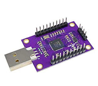
The mighty and very affordable FT232H breakout board.

This Breakout Board is inexpensive and gets your PC talking GPIO, UART ("serial"), SPI and I2C, as well as other useful protocols, really fast. You need to do some coding however; I used the PYFDTI python module. 

Last time we covered GPIO and UART, now let's see some more PY-FTDI programming examples to get SPI and I2C going.  To test this I wired the FT232H to an Adafruit 4725 I2C DAC Breakout board to see if I could see voltages on a scope. The MCP4725 (datasheet is here) is an breakout board I have used on many projects--it's easy to use and affordable. 

Wire it up like this:


Clip your scope lead to the output of the MCP4725 breakout board..... 

Then, run the sample code below on your PC. To see the output voltages move around, change the values in a.write (bytes) (to 0x00,0x00 for instance, or 0xFF, 0xFF) and re-run the script.

BTW, your MCP4725 may not be set to addr. 0x62 since the board can be configured to operate at different I2C addresses.  See the comment "You need 2 byte addr..." in the code example below. You'll need the right I2C address for your 4725 for the code fragment to work.


////////////////////////////////////

from pyftdi.i2c import I2cController

i2c = I2cController()

device = 'ftdi://ftdi:232h:0:1/1'


'''

YOu need 2 byte addr. of your i2c dookie.

use "i2cscan.py" to get the

address of your I2C device.

i2cscan.py is in the "tools" included with

pyftdi

However you need to modify i2cscan.py first.

find this line, then put your URL here:

argparser.add_argument('device', nargs='?', default='[YOUR-FTDI-URL-HERE]'

OK run the i2cscan.py script

output of that program is a grid with a single char, not a value.

Q: what do x and y axis in the grid mean?

A: it indicates the address where it found your I2C device.

to craft hex addr of device it's:0x(column row)

you knew that right?

'''

slave_port = (0x62)

i2c.configure(device)

a = i2c.get_port(slave_port)

#'0x0F,0XFF is full throttle'

#'0x00,0x00 means 0V from DAC out'

a.write([0x01,0xFF])


OK we have DC. But why stop there?  Modifying the code slightly produces a crappy ramp wave:


from pyftdi.i2c import I2cController
i2c = I2cController()


device = 'ftdi://ftdi:232h:0:1/1'


slave_port = (0x62)
i2c.configure(device)
a = i2c.get_port(slave_port)

#watch the line wrap on all these scripts....
#create a crappy ramp wave....
rList = [0,255,1,255,2,255,3,255,4,255,5,255,6,255,7,255,8,255,9,255,0xA,255,0xB,255,0xC,255,0xD,255,0xE,255,0xF,255]

#run it 1000x's
arr = bytearray(rList)
b = 0
while b < 1000:
    a.write(arr,relax=False)

    b = b + 1
 
Scope out looks like this:


SPI-ing on the FT232H: ...here's the wiring, for testing we use the FT232H and a Arduino UNO that's set as an SPI slave:


Code for the PC:
///////////////////////////

from pyftdi.spi import SpiController

#pinout from H232 for SPI
'''
ad0 SCLK to UNO pin 13
ad1 MOSI to UNO pin     11
ad2 MISO to UNO pin 12
ad3 CS0 to UNO pin 10
ad4 cs1 ... ad7 CS4.
'''

# Instantiate a SPI controller
# We need want to use A*BUS4 for /CS, so at least 2 /CS lines should be
# reserved for SPI, the remaining IO are available as GPIOs.
spi = SpiController(cs_count=2)
device = 'ftdi://ftdi:232h:0:1/1'
# Configure the first interface (IF/1) of the FTDI device as a SPI master
spi.configure(device)

# Get a port to a SPI slave w/ /CS on A*BUS4 and SPI mode 2 @ 10MHz
slave = spi.get_port(cs=1, freq=8E5, mode=1)
qq = bytearray([6,15])
# Synchronous exchange with the remote SPI slave
#write_buf = qq
#read_buf = slave.exchange(write_buf, duplex=False)
slave.exchange(out=qq, readlen=0, start=True, stop=False, duplex=False, droptail=0)
slave.flush() 
Code for the Uno: 
/////////////////////////////////
#include<SPI.h>
volatile int i = 0;
byte myArray[2];

void setup()
{
  Serial.begin(9600);
  pinMode(SS, INPUT);
  pinMode(MOSI, OUTPUT);
  pinMode(SCK, INPUT);
  SPCR |= _BV(SPE);
  SPI.attachInterrupt();  //allows SPI interrupt
}

void loop(void)
{
  if (i == 2)
  {
    int x = (int)myArray[0]<<8|(int)myArray[1];
    Serial.print("Received 16-bit data item from Master: ");
    Serial.println(x, HEX);
    i=0;
    Serial.println("=============================================");
  }
}

ISR (SPI_STC_vect)   //Inerrrput routine function
{
  myArray[i] = SPDR;
  i++;
}
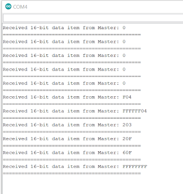
///////////////////////////// Serial output looks like it's working--yeh baby:

OK enough tests.....Here's a real-world example of the FT232H at work:

I attached an Analog Devices 9833 function generator IC downstream from the FT232H breakout board.  The 9833's data sheet is pretty hard to follow I think, but, a good "getting started" page going over the basics is here. And yes, you can get 9833's on an inexpensive breakout board in North America, assuming this Amazon post still works: here

There is an Arduino library for it, a library for programming the 9833 using C++, and on and on--it's everywhere!! But....we'll use Python.....

Yep, let's make some sine waves using PYFTDI and the FTDI232H:


Here's the code.  Comment/uncomment the 3.1Mhz etc. lines to get different frequencies.

from pyftdi.spi import SpiController

#pinout from H232 for SPI
'''
ad0 SCLK 9833 SCLK
ad1 MOSI to 9833 SDATA
ad2 MISO  (not used)
ad3 (not used)
ad4 SS to 9833 FSYNC
'''

# Instantiate a SPI controller
# We need want to use A*BUS4 for /CS, so at least 2 /CS lines should be
# reserved for SPI, the remaining IO are available as GPIOs.
spi = SpiController(cs_count=2)
device = 'ftdi://ftdi:232h:0:1/1'
# Configure the first interface (IF/1) of the FTDI device as a SPI master
spi.configure(device)

# Get a port to a SPI slave w/ /CS on A*BUS4 and SPI mode 2 @ 10MHz
slave = spi.get_port(cs=1, freq=8E6, mode=2)

cntrl_reset = [33,0]

#freq0_loadreg = [80,199] # 400hz.
freq0_loadreg = [120,00] #1.33khz
#freq0_loadreg = [123,FF] #3.1Mhz

cntrl_freq0write = [64,0]

phase0 = [192,0]

cntrl_write = [32,0]

send2_9833 = cntrl_reset + freq0_loadreg + cntrl_freq0write + phase0 + cntrl_write

print(send2_9833)

qq = bytearray(send2_9833)
# Synchronous exchange with the remote SPI slave
#write_buf = qq
#read_buf = slave.exchange(write_buf, duplex=False)
slave.exchange(out=qq, readlen=0, start=True, stop=True, duplex=False, droptail=0)
slave.flush()
 
Yep, We have Sine!


Wow, that's alotta sinegina....... get all code samples for this post from Github, here. Update 12-31-20 see the post here for another PYFTDI-9833 code example where you can enter in the frequency you want at output.

Enough...back to the day job....I will probably work more with the PYFTDI-9833 Function Generator code and hardware in a future post, even though there are plenty of projects/web sites that already tell you how use the 9833 to make a decent FG. Maybe a quad voltage controlled LFO?  

In the meantime, stay safe, have fun, don't breathe the f(tdi)umes.

Wednesday, December 16, 2020

FTDI232H BreakOut Board--The affordable USB Swiss Army Knife for Audio DiWHY! Part I: how to get started!!!

If shelter in place has made you a listless here's a suggestion: entertainment is an AliExpress click away. This time let's check out an interesting breakout board ("BoB"), the FT232H, get into the lab and have fun. 

This BoB costs next to nothing ( < $10USD!!) and advertises the ability to take in USB data and output SPI, I2C, UART, etc.--all extremely useful to AudioDIY.  

BoB's YER UNCLE? Breakout Boards are most often useful SMD chip(s) with minimal support circuitry on a tiny PCB. Pins are usually set at 100mils; prices are usually low; English documentation goes from good (Adafruit; Sparkfun) to none  (中国克隆!!)  

This FTDI232H breakout is no exception; get it from  HiLetgo and other Shenzhenronauts. I got one branded CJMCU-FT232H; you can get this from Amazon, assuming this link still works, here.  

Upon close inspection the CJMCU BoB is a FT232H chip, with minimal support circuitry, a regulator, and a timing crystal. Do the FTDI datasheets apply? Let's find out. 

First, I downloaded the datasheet for the FT232H.  FTDI is British (didn't know that) and the (English language!!!) docs for their FTDI chips are top shelf; find everything you ever wanted to know about the FT232H here--FTDI documented the hell out of this chip.   Good news--the FTDI docs apply to our BoB!!!


Next up: I needed the FT232H Windows drivers since I was going to use a Windows 10 desktop computer for this project. Zadig is useful for this; this free utility finds attached USB devices and lets you, the end user, select and install a handful of generic Windows USB drivers for discovered devices. Use Zadig to match your FT232H to the USB Windows driver required by your software--for this project it worked; but beware: you can also break your Windows 10 driver coinfigurations with Zadig--In short: as long as you're careful, Zadig is a useful utility and should be in your software toolbox.


Zadig for Windows. Click on options > list all to  see what USB devices are attached. Then you can change drivers. The blue box on the left shows the currently driver installed; green box is a pulldown of drivers you can install over existing. "Single RS232-HS" is the BoB being discussed in this post with the drivers needed by PyFTDI shown on the left. 

Update 1-3-21: I have found that Zadig's driver installations might break if you unplug the USB device and move it to another port. You have to install the correct libusb0 driver again for the new port.  However if you move the device back to the original USB port you still have to reinstall the driver again.  Not sure why this is, I am digging into it but the workaround right now is to always plug the FT232H into the same USB port every time, and be ready to reinstall the correct driver with Zadig as needed.   

Next we need software to make this work.  I used pyftdi for these tests, get that here; you will also need to install Python v3 (I used 3.9) if you don't already have it--download that here; then import the pyFTDI module (info on importing modules in Python is here.) 

PyFTDI's authors put a lot of work into their software--pyftdi has methods and properties that touch pretty much every feature of the FT232H chip, including changing values in the FT232H's eeprom. The PyFTDI documentation (here) is exhaustive; the pinout for the 232H board is on the PYFTDI pages is here; the pinouts match the CMJCU board's silks (which sadly are on the opposite side of the board vs. the BoB's LEDs).

The rest of this week's lab work will focus on making PyFTDI USB-to-whatever work in the simplest manner. PyFTDI includes tools (here) and Python code test examples, but the examples are complex; I'd like to keep this simple for now. 

First up: Let's see if we can see the FT232H BoB at all using pyftdi. Code for doing that with PyFTDI is easy:

##################

import pyftdi.serialext

from pyftdi.ftdi import Ftdi


Ftdi.show_devices()


##Available interfaces:

##STDOUT shows this: 

#ftdi://ftdi:232h:0:1/1   (Single RS232-HS)

####################

Happily: my FT232H Breakout Board is found, which means the Windows USB drivers, BoB, USB cables, etc., are OK. The odd URL above is used to identify the board in the rest of the code examples; your URL may be different; so run the "find devices" script first and note its output.  

With that done: Let's see if we can make this BOB "talk" UART.  It's Just two wires--TX->RX and ground, for the bench work I used the 232H for transmit and my trusty and well worn Arduino UNO for Serial receive. 

Tx for the 232 is AD0.....you may also need a 1K pullup from RX line to 5V....

Here is the PYFTDI code to make this go:

#########################

import pyftdi.serialext

port = pyftdi.serialext.serial_for_url('ftdi://ftdi:232h:0:1/1', baudrate=9600)

# Send bytes

port.write(b'Hello Arduino 9I am still here')

######################

Here is the sketch for the Arduino uno for this--for simplicity, a "9" in the string above returns a carriage return in the Arduino's serial output window:

////////////////////////////////////////

//show me what is coming into RX port

int incomingByte = 0; // for incoming serial data

int p = 0;

void setup() {

  Serial.begin(9600); // opens serial port, sets data rate to 9600 bps

}


void loop() 

{

  // reply only when you receive data:

  if (Serial.available() > 0) 

        {

        // read the incoming byte:

        incomingByte = Serial.read();

          // say what you got:   

            p = (incomingByte);

            // 9 works as carriage return. 

            char c = p;

            if (c != '9')

                        {

                        Serial.print(c);

                        }

            else

                        {

                        Serial.println();

                        }

            } // end if

} //end main

////////////////////////////////////////

Easy?  Yes and no. I got this to work, the string entered into "port.write" would show up in the arduino IDE's serial output, but I spent an entire weekend day trying to figure out why, when the FTDI BoB and Uno were both online at the same time, I couldn't upload sketches to the Uno--it would get hung up on "uploading".  

This could be many things: USB conflict? Pullups? Cabling? Noteably, I had the same issue even when trying to upload from a Mac--which of course is a completely different PC! 

I finally found a link here that explained it: don't use RX at all when trying to upload sketches (which makes no sense; SPI is used to program the UNO, not serial? So there is something going on inside the UNO and Nano I still don't understand). 

From there I hit upon a workaround: unplug the UNO's USB, which kills a forever hung upload; remove the RX line, reset the Uno, and upload the sketch again. Now, with new code inside the UNO, plug back in the RX line. That worked every time. 

UPDATE: 2-8-21. to figure out why this didn't work, read the UNO schematic! Programming for  Arduinos and Arduino clones is via serial, not SPI; the USB signal is translated to serial by a CH340, FTDI, or 16u2 chip, which then sends the programming info to the Arduino's UART inputs. More detail about how this works can be found hereSo yes, shorting the MPU TX pin to ground through a 1K resistor etc. is going to break programming for an Arduino.

This also means that for any AVR loaded with Arduino Optiboot, you can use the FTDI BoB's UART outputs to program the MPU instead of USB. Go here to see how to do this from the Arduino IDE.  If your PC can't recognize a CH340 USB to UART chip due to a driver problem, this is a viable workaround.

Next up: GPIO. The pyftdi docs tell us to check the test examples (here) but I couldn't find examples for  GPIO. But figuring out how to use GPIO ("bit banging" as it's often called) with the FTDI BoB wasn't difficult:


I tried to do 2 things: flash an LED (of course!) and create a basic waveform on my scope using nothing but the BoB's GPIO pins and ground.  Success with both, here is the Python code:

For LED flash:

###########################

from pyftdi.gpio import GpioAsyncController

import time


device = 'ftdi://ftdi:232h:0:1/1'


gpioa=GpioAsyncController()


x = 0

gpioa.configure(device, direction=0b11111111)

# all pins as output; use AD0-7

#pins AC0-9 don't work with bit bang GPIO?


#flash LED 4 times


while (x != 4):

    gpioa.write(0b00000000)


    time.sleep(1) # Sleep for 1 second

    gpioa.write(0b11111111)

    time.sleep(1) # Sleep for 1 second

    #print("iter value is: " + str(x))

    x=x+1

############################################

and for generating basic waveforms on a scope:

#############################################

#FT232H as GPIO clock gen.


from pyftdi.gpio import GpioAsyncController

gpioa=GpioAsyncController()

device = 'ftdi://ftdi:232h:0:1/1'

gpioa.configure(device, direction=0b11111111)


bytes = []


#works with pins AD0-AD7

#output goes from hi-z to ground, so you may need to set up a pullup.

#you might need to buffer the output of AD0 (with transistor?)  depending on what you have downstream. For my scope I didn't need it.

#dont remember why I commented next line but

#it isn't needed.

#gpioa.open_from_url(device, direction=0b11111111)


freq=100000 #keep this reasonable. < 500K.

secs = 5 # number of seconds to run clock.

#resulting frequency of on followed by off is half of freq.

#so we mult it by 2....

gpioa.set_frequency(freq*2)


#GPIO outputs are sent as an array of bytes.

#below we create 10K bytes alternating off and on, and output the data enough

#times to create a secs second pulse.

a = range(0,10000)


for b in a:

    if b % 2 == 0:

        bytes.append(0x0)

    else:

        bytes.append(0x1)


times = int(freq/10000)

print(times)

#WRITE YER BYTES FOR "secs" SECONDS

a = range(0,times*secs)

for xx in a:


   gpioa.write(bytes)

##########################


The result is a good-enough squarewave whose frequency is determined by the freq variable in the code above. For me the frequency of the square wave generated (anything between about 10K and 500K) was accurate to a few decimel places. Nice.


Update 3-10-21 it is pretty hard to tell from the PYFTDI documentation, but for BitBang/GPIO, you can only (easily) use the AD0-7 pins. So the bus is only 8 bits wide. AC0-7 cannot be easily addressed.

Waveem off: let's not stop there; with a simple 8 bit resistor-ladder DAC we can easily get other waveforms from the FT232H BoB's GPIO pins.

Basic 8 bit DAC. Webpage on how this works is here. For this POC, 1% metal-film resistors are good enough.


I added pullups on the upper left....

Quick 8 bit DAC ladder is back from China. Get Eagle files for 8 bit DAC for this post from Github, here.


Wiring for this....


With this 8 bit DAC in hand--simple, it's just some resistors, we can make basic waveforms like triangle and ramp by hooking each data line from the FT232H to the DAC's inputs.


////////////////////////  GPIO RAMP
 

from pyftdi.gpio import GpioAsyncController
gpioa=GpioAsyncController()
device = 'ftdi://ftdi:232h:0:1/1'
gpioa.configure(device, direction=0b11111111)

bytes = []

#works with pins AD0-AD7
#output goes from hi-z to ground, so set up a pulldown.
#you might need to buffer the output of AD0 (with transistor?)  depending on what you have downstream.

#gpioa.open_from_url(device, direction=0b11111111)
#resulting frequency of on followed by off is half of freq.
#so we mult it by 2....

freq=15000 #keep this reasonable.
rampfreq = freq * 256
secs = 5 # number of seconds to run clock.

gpioa.set_frequency(rampfreq)

endtime = freq*secs
print(endtime)

#WRITE YER BYTES FOR "secs" SECONDS

a = range(0,endtime)


my_list = list(range(0, 255))


tribyte = bytearray(my_list)


for xx in a:

   gpioa.write(tribyte)

gpioa.close()

////////////////////////  GPIO TRIANGLE

from pyftdi.gpio import GpioAsyncController
gpioa=GpioAsyncController()
device = 'ftdi://ftdi:232h:0:1/1'
gpioa.configure(device, direction=0b11111111)

bytes = []
 
freq=10000 #keep this reasonable.
secs = 10 # number of seconds to run clock.

gpioa.set_frequency(freq*2)

times = int(freq/100)

print(times)

#WRITE YER BYTES FOR "secs" SECONDS

a = range(0,times*secs)

my_list2 = list(reversed(range(1,254)))
my_list = list(range(0, 255))
list3 = my_list2 + my_list


tribyte = bytearray(list3)


for xx in a:

   gpioa.write(tribyte)

gpioa.close()

////////////////////////


Gogetim: Get the python and Arduino code this post from github--here.

Shukran Breakout board for CMJCU FTDI232H Breakout board.....


Update 3-10-21 I have found that breadboarding with the CMJCU BreakOut Board is a bit tricky due to its width.  So I went the github page here and got gerbers for the "Shukran" which is a breakout board for the breakout board.  Got that PCB made, back, built. Easy to assemble; the only confusing thing for me was that the switching 5V power is tied to AC08 which can't be easily enabled through PYFTDI, and the shukran docs say "consult FTDI". OK: from FTDI docs it looks like you need to enable this by changing firmware in the FTDI chip's eprom.  If I built this again I'd probably leave the MOSFET, LEDs and resistors for this feature out, but overall the board works fine, and since AC08 can be used for things like 7.5mhz clocks, maybe consider using this feature down the road.

That's it for now....this is becoming a long post....next time we'll finish this off with simple examples for SPI and I2C. Update: posted!  go here. Until then: BoB well and live.  See ya.

Wednesday, December 9, 2020

6502 SBC and the Chip Select Epiphany

What did you do during Covid? Me, not much.....but I have been trying to understand computers at a deep level--to augment my digital and hybrid design skills, e.g., ones based on SBCs like a Raspberry Pi, I figure it's a good time to learn how computers really work. 

How phones really work. Analog ones anyway.

Single Bored Computer: where to start? I figure learning retro computer technology, circa say 1980, would help. Modern hardware, with its improved performance, multiple CPU cores, complex GPU's, and so on, follows the same design principles as retro systems but are a lot more complex. Let's start with the old designs. 

OK, what retro rig? After experimenting with an RCA1802 I settled on the Western Devices 65C02 CPU for this learning process, since it's still in production (!), can be clocked at a snails' pace, and is well documented. 

65C02 research led me to a tremendous series of vids from YouTube legend + content creator Ben Eater; he built a 65C02 SBC on breadboards.  Wow! If you are interested in understanding how computers really work, watch his vids; then watch some of them twice. This guy is the real deal.

The mighty Mr. Eater must have put a ton of work into his vids; least I can do is buy his kit (here). "Hands on helps". But you know how I hate breadboarding, so I bought a PCB for the Eater design from PBCWay as well, here.  Here it is partially assembled:

The Eater 6502 parts kit: got that here.....partially assembled PCB, and an SBC external timer. A useful logic probe, based on an Arduino Mega, is also part of the BE 6502 project, vid for that is here.


So far so good, but after finish all the fab, it took me about 3 evenings to get the SBC working, mostly because I rushed and made mistakes. Never rush.  

Stupid mistakes let me count thy ways. First, I got an older version of the PCB, i.e., I clicked "add to cart" to save myself about 2 minutes--but instead, I should have read the project's webpage, downloaded the REV-B gerbers and gotten the REV-B PCB fabbed from that. The PCB's designer clearly states REV-B solves some design issues with REV-A, but I missed it. The author also clearly states: to get REVA to work I needed to add a 3K resistor to the bottom of the board, or the BE pin on the 6502 won't be held high, but, well, I missed that too. Until I used Sigrock Pulseview to determine the 6502 BE pin was kaput, and added the aforementioned kludge, I got zilch from the CPU. Time wasted: maybe 2 hours. Very nice! 

I also put all the LEDs in backwards and also flipped the SBC's reset switch 90 degrees. I see these little 4mm switches all the time but did I really know how their contacts were laid out?  No. 4mm switches are laid as per my drawing below: flip the switch 90 degrees and it won't work.  


During fab I also had a scary moment; I decided to replace the RAM socket with a low profile 28 pin ZIF I had in my junk box, but lifted up a critical trace in the process.  


Fortunately when I soldered in the ZIF and fixed every other mistake everything worked, which means the RAM socket trace must have still made contact--I got lucky. It was a frustrating few evenings, but, troubleshooting the REV-A board, using my PIVISA enabled bench tools, adding the missing BE kludge resistor and correcting other stupid mistakes proved educational; fixing something new almost always is.

Working SBC.  


My current setup for 6502 SBC action. Clockwise from left: ROM burner, LCD, timer, breadboard, and Arduino Mega clone used as a logic probe. In the center is the 6502 SBC.


OK, so, beyond practicing patience during fab, what else did I learn? The crux of the biscuit is understanding basic Von Neumann architecture. That's the internal design most (if not all?) PC's nowadays use, including the Eater SBC.  

(Von Who? No not this guy:)

Not me--"yes I worry".


(Not this guy either:)

Wasn't involved in computer design as far as I know but, hacked strat clones, and is extremely important.


This guy!!

John Von Neumann, who led the team that came up with the basic architecture of a modern PC. All hail-- outrageously brilliant dude--"The Van Halen of Computer Hardware". Fun video re: JvN is here.

In this case: The Eater SBC's CPU, RAM, ROM, and peripherals share common elements: for instance, data, address, and read/write lines. What this SBC project drove home and what I felt I didn't understand is how each device (a RAM chip, a ROM chip, a graphics device, etc.) on the bus is enabled or disabled.  

It's pretty simple: we use logic to trap a range of memory addresses then upon a match select a chip or device so it can read from or write to the shared bus, allowing the chip to do useful things. Otherwise: deselect the chip or peripheral so it leaves the data and bus alone. Once the chip is selected the CPU can communicate other things to it, such as whether to read data from it (eg: OE or "output enable" = low), or write data to it (e.g.: WE or "Write enable = low"). The Eater SBC uses a single 74HC00 chip to trap addresses and uses the 7400s' outputs for selecting the computer's various memory ICs as well as the LCD display for Read/Write madness. 

These logic values, chosen when the PC or MCU was laid out, determines the device's memory map, a computer science term I never really understood. Now I think I get it.

So yes: this week's great chip select epiphany can be summed up in an abbreviated, back of the napkin drawing:


From here we can dig into how each chip, CPU, peripheral etc. works, giving us a way to understand things at a deep level. 

Timing has to be considered--see the vid here--just because a chip or device is selected doesn't mean it will act quickly or slowly enough to make everything else on the bus happy. And of course, you need to understand how the guts of the CPU and attached devices work--study those data sheets--to be able to write useful assembly code. 

Going forward: the PCBWAY-PCB for the REV A Eater 6502 SBC PCB has an expansion bus if you will--it brings useful signals out to a 40 pin header, and better still, there is room in Mr. Eater's SBC design to trap unused memory addresses (say 4000-4FFF?) to add more peripherals, perhaps something audio focused? But that's for a later post. 

OK enough for now. It's Covid so i can't get on the local bus, but now, I can most-def get on the PC's bus. Which means yes, there are fumes, but at least they aren't diesel. See ya.


Anything to Clock Subcircuit

Readers:  If you want to build the project featured in today's post, please go to  PCBWAY's  Community pages --a gerber ready to dow...