If you're an audio geek like me and have been sheltered in place for the past frigging 50 years due to the global pandemic, maybe your entertainment values have changed?
To wit: the $35 I would have spent going to a foreign movie with my psychiatrist girlfriend remains in the bank.
So let's have fun with that $35USD--i.e., audio DIWHY geek fun--and at the same time we'll get small.
Ditch the dubbers, elmo: During my quest for I2S without issue I found the video here: Teensy Audio.
So let's have fun with that $35USD--i.e., audio DIWHY geek fun--and at the same time we'll get small.
 |
| Digital Audio--super powerful MPU--stereo headphone jack and amp--tons of free example sketches--stereo analog I/O on board--all for $35 USD? Are you frigging NUTS? No, it's true! All hail Stoffregen and Coon! |
TEENSY!
I started down the Teensy rabbit hole while researching I2S (more on I2S in upcoming posts; in a nutshell it's a common digital protocol for sending audio data between devices). I wanted to better understand how I2S works, and how to use it in projects, but feared chasing digital synch issues, PC crashes, problems with aliasing, and general fear and loathing. These were things I had to contend with during the many years I worked in audio for film post production--and this is supposed to be fun--so, no, let's not go there again.Ditch the dubbers, elmo: During my quest for I2S without issue I found the video here: Teensy Audio.
Wow! It has everything already built in: I2S, A to D, D to A, an SD card reader, the codecs you'll need, an affordable MCU with some effects already preprogrammed in, a comprehensive library, even a 3.5" amplified stereo handphone jack--again: are you kidding--plug it in an go right?
Is it all too easy? I needed to find out.
I bought a teensy 4.0 direct from the manufacturer, pjrc.com, along with their audio adaptor board which arrived neatly packaged and boxed a few days later.
My goal was to get the Teensy 4 working, program it from the Arduino IDE, run the audio examples, then record the examples and post them online--there are many video already about this technology, but I could find few that clearly showed how this little spud really sounds when put to the test.
I bought the version without pins. What else am I doing to pass the time?
Which meant: solder all the pins and get the audio adaptor board working with the teensy MCU.
Is it all too easy? I needed to find out.
I bought a teensy 4.0 direct from the manufacturer, pjrc.com, along with their audio adaptor board which arrived neatly packaged and boxed a few days later.
My goal was to get the Teensy 4 working, program it from the Arduino IDE, run the audio examples, then record the examples and post them online--there are many video already about this technology, but I could find few that clearly showed how this little spud really sounds when put to the test.
 |
| The legendary Teensy Audio . I put the audio hat on top so I could still easily jam the teensie itself into a breadboard, but I think PJRC wants you to put the shield below the Teensie, so you can easily see its legends. |
STACK EM UP RAWHIDE
I bought the version without pins. What else am I doing to pass the time?Which meant: solder all the pins and get the audio adaptor board working with the teensy MCU.
But still have the shield removable if needed later.
I looked around the web for the best practice for this MCU to shield connection and to my astonishment couldn't find it.
I looked around the web for the best practice for this MCU to shield connection and to my astonishment couldn't find it.
Time to roll my own? How hard could this be?
Here is what I came up with:
Needed: the teensy 4, its audio adaptor board, soldering rig + solder wick; male to male breakaway header pins and male to female breakaway header pins.


Step One: install male/male pins to the teensy, as you would with any MPU:

Step Two: This is important!! Use solder wick to get rid of any extra solder that ended up on the "shield side" of the Teensy. In my case I am wicking off extra solder on top of the teensie. The adaptor board has to lay flush, so you want to make sure this solder job is completely tidy and minimal without "solder Hersheys kisses" getting in the way.
Step Three: solder the M/females edge connectors to the bottom of the audio shield (making it easy to breadboard the teensie itself with the audio shield attached) or top (makes it easier to get at the audio adaptor's I/O). This time, I chose female headers on the shield's bottom:
 Step Four: mate 'em up.
 SIMPLE RIGHT? You will end up with something like what you see below. Um, no. I wasted a fair amount of time getting this simple setup to work.....I consider myself pretty good at fab, but I had undersoldered a couple of pins after wicking; thus the shield didn't initially work when it came time to breadboard. But! if I used too much solder the audio adaptor wouldn't sit flush with the MCU and the audio would cut in and out.
Here is what I came up with:
Needed: the teensy 4, its audio adaptor board, soldering rig + solder wick; male to male breakaway header pins and male to female breakaway header pins.


Step Two: This is important!! Use solder wick to get rid of any extra solder that ended up on the "shield side" of the Teensy. In my case I am wicking off extra solder on top of the teensie. The adaptor board has to lay flush, so you want to make sure this solder job is completely tidy and minimal without "solder Hersheys kisses" getting in the way.
 |
Step Three: solder the M/females edge connectors to the bottom of the audio shield (making it easy to breadboard the teensie itself with the audio shield attached) or top (makes it easier to get at the audio adaptor's I/O). This time, I chose female headers on the shield's bottom:


This takes some pretty careful soldering.
Next time I will make sure the audio adaptor goes below the Teensy, although I figure I may have the same challenges?

Next, I needed analog breakouts: here is what I came up with. The 3.5" jacks board was left over from another project.....
But wait! We are not done with the Teensy hardware.
The audio board has provisions for a flash (non-volative storage) or RAM (read/write; loses data at power off) chip. The latter assists in getting longer (1500ms) delay times from the board, which is what I want--information about these chips can be found toward the bottom of the page here.
I ended up buying ram chips direct from Microchip and soldering one on. It would have been easier to do this before the headers were installed. Next time.

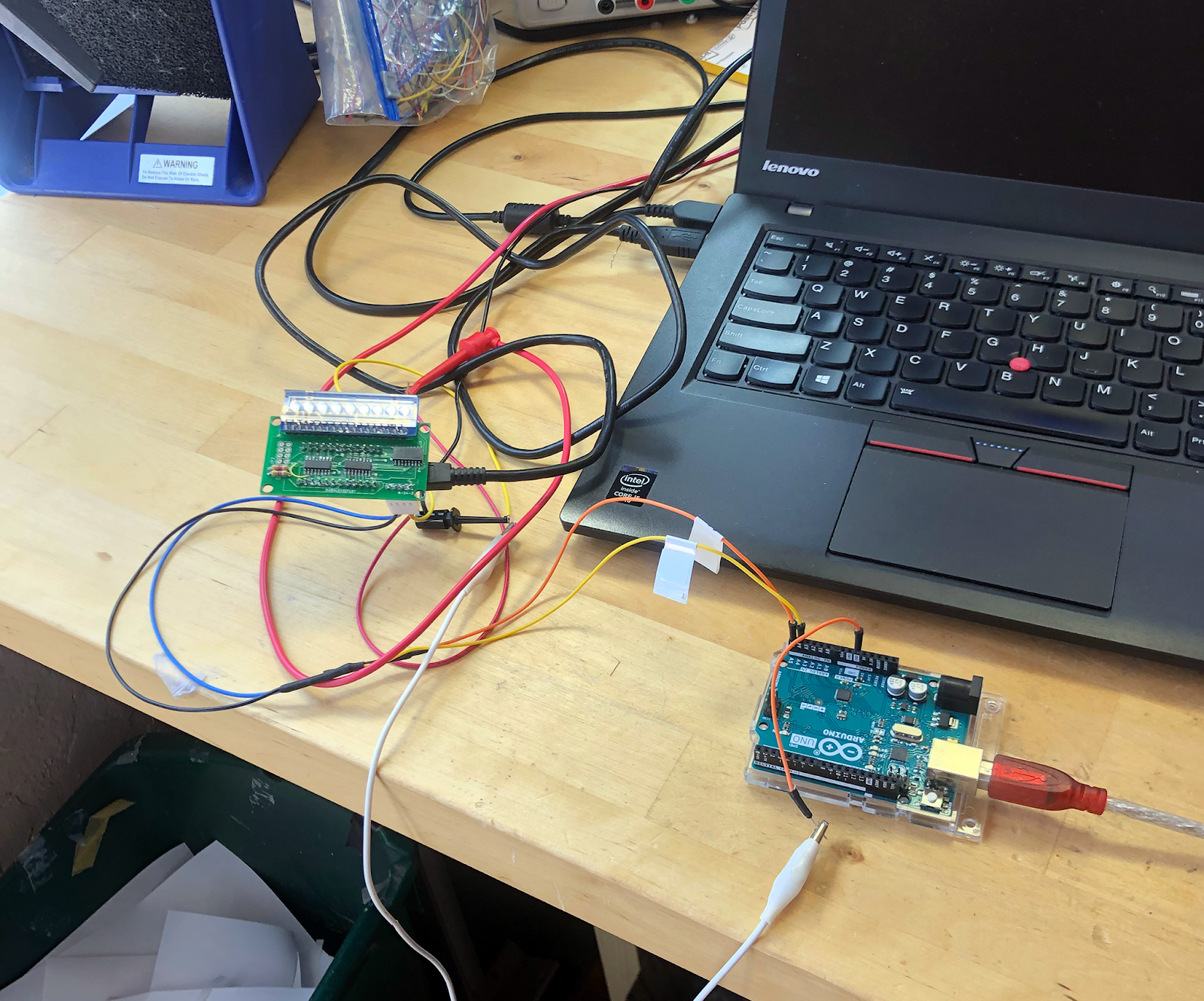
Next, I needed some pots n' switches to goose the analogRead() statements in the sample sketches.
The many online tutorials (e.g.: here) use breadboarded parts for this, but I hate breadboarding, so I built this out of perf, which I like only a bit better:

Now let's breadboard the Teensy + shield and wire it up to a DAW using USB:

And set up a rig for testing, screwing with the code, etc. which goes like this:
This proved to be a tiny bit trickier for me vs. the hardware part.
The teensy USB setup is not like what I've seen elsewhere. Yes, you use the same USB cabling, the same Arduino IDE, the same laptop, and the rest of it, but you also need special software from PJRC called their "loader" to get the Teensy to download sketches.

Next, I needed analog breakouts: here is what I came up with. The 3.5" jacks board was left over from another project.....
 |
The audio board has provisions for a flash (non-volative storage) or RAM (read/write; loses data at power off) chip. The latter assists in getting longer (1500ms) delay times from the board, which is what I want--information about these chips can be found toward the bottom of the page here.
I ended up buying ram chips direct from Microchip and soldering one on. It would have been easier to do this before the headers were installed. Next time.

 |
| Thank goodness for scotch tape.... |
 |
| Not the neatest SMD solder job ever, but hey, it works. |
Next, I needed some pots n' switches to goose the analogRead() statements in the sample sketches.
The many online tutorials (e.g.: here) use breadboarded parts for this, but I hate breadboarding, so I built this out of perf, which I like only a bit better:

Now let's breadboard the Teensy + shield and wire it up to a DAW using USB:

And set up a rig for testing, screwing with the code, etc. which goes like this:
 |
| The IKEA steak knife on the left is the unofficial "reboot your MPU tool" for Teensy Audio. Otherwise you can't easily get to the really small reboot switch when the audio adapter board is on top, and, you're going need to get to the reboot switch from time to time. |
UPLOADING CODE
With all the hardware up and running it's time to get the example sketches onto the Teensy....This proved to be a tiny bit trickier for me vs. the hardware part.
The teensy USB setup is not like what I've seen elsewhere. Yes, you use the same USB cabling, the same Arduino IDE, the same laptop, and the rest of it, but you also need special software from PJRC called their "loader" to get the Teensy to download sketches.
Next you have to install special software so your Arduino IDE can recognize teensy hardware: see the "Teensyduino" information here.
I tried to get the loader and Ardunio IDE working on Fedora Linux--that's where I do most all of my coding-- and couldn't get it to work after about 2 evenings of trying. No, Captain Ubuntu, I didn't try compiling from source code which probably would have worked--sorry cap, that would have been too easy.
I went to Mac OS-X Sierra and everything worked right away, but with one strange detail--after you power cycle things, for the first upload from OSX to the Teensy, you (often?) have to press the tiny white button on the teensy MCU to initiate the upload. (see the steak knife in the photo above--that's why it's there). Note that this momentary switch in the stack I built for this post is obscured by the shield--sorry.
The Teensy then can run the sketch.
After that it all works--no more need to press the white button. Until the next time you power cycle things. Then you have to hit the tiny button again--but just once.
This stumped me for a bit.
Also: to have the serial I/O work (you know, Serial.begin(); etc etc), you have to choose the "Teensy USB port" within Arduino IDE > tools > port; but you don't have to do that to program the device.
OK.....
Another thing that got me really interested about the Teensy is its web based GUI. PJRC has a web UI to assist coding your own effects and audio projects that they call the "audio design tool". Take a look at that here.
My goodness! You can chain things together, create feedback loops, and even rename the objects, sort of like a small web version of Reaktor. Then hit the EXPORT button and the Arduino sketch object instantiation is done for you--copy the code into your sketch. And!!! you can take an existing Teensy Audio sketch, such as code in the PJRC provided examples, import the sketch into a blank web UI, and the UI will create the Reaktor-like object flow you can then review.
It all works! Now, that is really cool.
But wait--proving once again there are still mosquitos in paradise: the GUI is extremely helpful but it won't write all your code for you. In fact if you just paste the auto-generated code into a sketch, upload it to the Teensy, and expect to hear sound, forget it. You won't.
For instance: using the TA UI tool, I created this very simple stereo mixer:
And then EXPORTED it to a sketch.....all code you see at the top of the sketch was pre-rolled.
To get this to work, I had to create the code you see in setup{} and loop{}--the GUI only created the objects and #include statements you see at the top of the sketch.
Fortunately between the Teensy's example sketches, information you get from PJRCs documentation, and what you might glean from what seems like a gazillion youtube "howto" vids, you can finish your code and get it working reasonably quickly.
/////////////SIMPLE TEENSY STEREO MIXER/////////////////////
#include <Audio.h>
#include <Wire.h>
#include <SPI.h>
#include <SD.h>
#include <SerialFlash.h>
// GUItool: begin automatically generated code
AudioInputI2S i2s1; //xy=244,74
AudioMixer4 mixer2; //xy=369,169
AudioMixer4 mixer1; //xy=374,35
AudioOutputI2S i2s2; //xy=506,72
AudioConnection patchCord1(i2s1, 0, mixer1, 0);
AudioConnection patchCord2(i2s1, 1, mixer2, 0);
AudioConnection patchCord3(mixer2, 0, i2s2, 1);
AudioConnection patchCord4(mixer1, 0, i2s2, 0);
AudioControlSGTL5000 sgtl5000_1; //xy=90,51
// GUItool: end automatically generated code
// COOL, BUT I STILL HAD TO CODE SETUP{} AND LOOP{} BY HAND:
void setup() {
//you need this or no audio!
AudioMemory(8);
//and this!!!
sgtl5000_1.enable();
}
void loop() {
//Mixer properties
// mixer(x,y)
// x is mixer input, so for us, 0
//y is gain:
//0 = no audio
//1 = unity
// >1 gain
//goes to 32000+, that's some serious damn gain!
mixer2.gain(0, 1);
mixer1.gain(0, 1);
}
You can also get a zipped copy of the sketches used (most of the PJRC examples were modified slightly to fit my I/O setup) here.
The gear used for the demo recording: OSX mac running Ableton 10 suite; Apologee Duet ADDA; the Teensy; unbalanced out to Rane SM82 with unbalanced loop sends to a Tascam SS-R200.
In other words, as simple as I can make this.
The chorus/flange is gritty and I didn't like its sound much; tweaking the example sketch--I feel I tried a lot of things--didn't get me much improvement.
For the other FX, I hear hiss and noise--some of the noise isn't Teensy's fault I think; I could have spent more time optimizing levels to get rid of some of the noise, but overall I needed to get this done as simply and quickly as I could, so there you go.
Overall, I thought the reverb, filters, delays, etc., were pretty damn good--definitely good enough to put in series with other audio effects you might dream up--need five 12db/octave bandpass filters in parallel for a specialized EQ? Use a teensy audio--boom, done, here it is.

The Teensy Audio's chorus/flange implementation was a bit weak, and I have a few minor gripes about how the hardware is laid out (such as silk legends, could they be on both sides of the audio board?) but beyond that, this is one of the greatest, if not the #1 GREATEST, DIY/Maker audio development products I've ever seen. It could cost 3x as much and arguably still be a great deal, but as of the time I wrote this post, it's $35USD?
THE TEENSY AUDIO DESIGN TOOL
Another thing that got me really interested about the Teensy is its web based GUI. PJRC has a web UI to assist coding your own effects and audio projects that they call the "audio design tool". Take a look at that here.My goodness! You can chain things together, create feedback loops, and even rename the objects, sort of like a small web version of Reaktor. Then hit the EXPORT button and the Arduino sketch object instantiation is done for you--copy the code into your sketch. And!!! you can take an existing Teensy Audio sketch, such as code in the PJRC provided examples, import the sketch into a blank web UI, and the UI will create the Reaktor-like object flow you can then review.
It all works! Now, that is really cool.
But wait--proving once again there are still mosquitos in paradise: the GUI is extremely helpful but it won't write all your code for you. In fact if you just paste the auto-generated code into a sketch, upload it to the Teensy, and expect to hear sound, forget it. You won't.
For instance: using the TA UI tool, I created this very simple stereo mixer:
 |
| DO NOT FORGET! the SGTL5000_1 object on the left, or your sketch won't work! |
And then EXPORTED it to a sketch.....all code you see at the top of the sketch was pre-rolled.
To get this to work, I had to create the code you see in setup{} and loop{}--the GUI only created the objects and #include statements you see at the top of the sketch.
Fortunately between the Teensy's example sketches, information you get from PJRCs documentation, and what you might glean from what seems like a gazillion youtube "howto" vids, you can finish your code and get it working reasonably quickly.
/////////////SIMPLE TEENSY STEREO MIXER/////////////////////
#include <Audio.h>
#include <Wire.h>
#include <SPI.h>
#include <SD.h>
#include <SerialFlash.h>
// GUItool: begin automatically generated code
AudioInputI2S i2s1; //xy=244,74
AudioMixer4 mixer2; //xy=369,169
AudioMixer4 mixer1; //xy=374,35
AudioOutputI2S i2s2; //xy=506,72
AudioConnection patchCord1(i2s1, 0, mixer1, 0);
AudioConnection patchCord2(i2s1, 1, mixer2, 0);
AudioConnection patchCord3(mixer2, 0, i2s2, 1);
AudioConnection patchCord4(mixer1, 0, i2s2, 0);
AudioControlSGTL5000 sgtl5000_1; //xy=90,51
// GUItool: end automatically generated code
// COOL, BUT I STILL HAD TO CODE SETUP{} AND LOOP{} BY HAND:
void setup() {
//you need this or no audio!
AudioMemory(8);
//and this!!!
sgtl5000_1.enable();
}
void loop() {
//Mixer properties
// mixer(x,y)
// x is mixer input, so for us, 0
//y is gain:
//0 = no audio
//1 = unity
// >1 gain
//goes to 32000+, that's some serious damn gain!
mixer2.gain(0, 1);
mixer1.gain(0, 1);
}
SHUT UP AND LINK THE SOUND FILE!
OK, it's here. the sound demo is as bare bones as I could make it--there are no attempts to synch the delay to the beat of the loop for instance. My goal here is remind myself six months from now how this thing sounds....that's it.You can also get a zipped copy of the sketches used (most of the PJRC examples were modified slightly to fit my I/O setup) here.
The gear used for the demo recording: OSX mac running Ableton 10 suite; Apologee Duet ADDA; the Teensy; unbalanced out to Rane SM82 with unbalanced loop sends to a Tascam SS-R200.
In other words, as simple as I can make this.
The chorus/flange is gritty and I didn't like its sound much; tweaking the example sketch--I feel I tried a lot of things--didn't get me much improvement.
For the other FX, I hear hiss and noise--some of the noise isn't Teensy's fault I think; I could have spent more time optimizing levels to get rid of some of the noise, but overall I needed to get this done as simply and quickly as I could, so there you go.
Overall, I thought the reverb, filters, delays, etc., were pretty damn good--definitely good enough to put in series with other audio effects you might dream up--need five 12db/octave bandpass filters in parallel for a specialized EQ? Use a teensy audio--boom, done, here it is.

TO TEENSY OR NOT TO TEENSY? TO TEENSY!
Or: what did I think? Ha! It's a blog so I can say anything I want right?The Teensy Audio's chorus/flange implementation was a bit weak, and I have a few minor gripes about how the hardware is laid out (such as silk legends, could they be on both sides of the audio board?) but beyond that, this is one of the greatest, if not the #1 GREATEST, DIY/Maker audio development products I've ever seen. It could cost 3x as much and arguably still be a great deal, but as of the time I wrote this post, it's $35USD?
Again: Are you kidding me?
Using stock or slightly modified sketches you can quickly create some reasonably good effects like reverb and delay, and with some imagination, creative coding, and tweaking, who knows what someone might come up with. There are 16 tons of creative possibilities here.
I felt after a bit of a learning curve coding got pretty fast.
And of course I haven't even touched on a lot of the other things this device can do--synthesizer module sims, audio analysis, and a lot more.
Overall: I figure PJRC put a butt ton of work into their hardware and software--with a great amount of passion--and it shows. PJRC should win the nobel prize--they have my nomination anyway--yes, This teensy>audio thing is that good. If you are into MCUs, DIY, and audio, run, don't walk, and get this thing.
For me, it's beyond hours of fun--Teensy Audio is going to change things. Yow!