Thursday, February 29, 2024

AudioDiWHY Moog HPF clone--"WFTBSLC."

The video here got me started on this project--cool sounding filter. Can I build one too?

Moog HPF--looks OK, works not so OK....

Sure I can. 

EFM Schematic is here--video and online posts say to add a few 22pF caps; I also added variable gain at audio input and output.  

It was a fair amount of work in Kicad to make sure everything lined up, but I thought I got it right, and off the gerbers went to this blog's patient sponsor, PCBWAY.

Whiz and bang, back came the boards:

To make the layout sane, I used 3 boards--main board, pots and jacks board, and a front panel.

Before soldering--did everything line up? Yes. Good start. 

I got building....

Taped down the boards to the bench; used my microscope (post here) to solder SOIC IC's.

Oh yeah, SOIC's on both boards....

main board done.

ready to start soldering the pots; Board in the center is the "jacks n pots"; it also has an OP07 to buffer the module's audio output.

Almost ready to test...

Two evenings--Built!

I put the project down, I needed a break. 

I remember walking up the stairs to my bench the next evening thinking--I had not had a "work the first time" (W.F.T) moment in a long time, would I get lucky?  

Probably not.

Fired it up, yes, the thing passed audio. Good!

yes, mod1 and mod2 swept the filter.  Good!

Yes, the Q adds a (slightly) buzzy "rez" sound to the filter. Good!

But....but...BUT! 

after time at the bench and in my rack--sadly, the filter S.L.C. --

"sounded like crap".  

Crap?  Yes, crap. Big, stinky, BART commute seat type crap. 

Better out then in? Nope.

To whit: SLC (int w; int* s; s = &w;)

The filter blocked all audio too frequently--I didn't think this was because only dogs could hear whatever frequencies the filter was passing....Instead--there was something more fundamentally wrong, like at many sweep settings the output was getting slammed to an op amp rail..  

When sweeping the cutoff frequency, often only a fraction of cutoff settings--sometimes 9 to 10 o'clock on the frequency pot--would pass audio at all.  Not good.

In spite of adding an attenuator at input and adjustable gain at output, I often had terrible distortion and level mismatches.

Mod1 and Mod2 interacted with one another--this might be a design "feature"?

"Q" worked but lacked the pleasing whistle-like resonance of the filter in the video.

In general, I was extremely disappointed in my build of this filter so far--

Hence the entire acronym:

WFTBSLC: the confusing acronym in the subject of this post.


"Worked First Time but Sounded like Crap".

Marvey.

Where did I go wrong?

A mistake somewhere--maybe a resistor value was incorrect? Perhaps? probably?

It could be a mistake in the traces as well, I have definitely made both mistakes before.

I didn't match transistors, and maybe I should have? This was due to laziness, and I read you must match transistors for Moog ladder designs to sound, well, Moog-like.  

But to me, this sounded a lot worse than transistor mismatching.

Something wrong with the resonance loop?  Maybe. Probably. 

I will wait a few days, maybe more, then go back to work on it. 

Hopefully it's a dumb mistake and will be easily fixed. 

Probably not.

I have signed up for some additional DIY audio forums, maybe some folks there will help me get this working?  

One of the experienced builders at my geeky Meetup said to reflow the cap solder joints. Tried that. 

Nope.  Still SLC.

I will not be defeated!  Until next time: DBTF.

update 3-11-24: after going over the build with a scope and DVM, I found no build issues but did find a few mistakes in the layout.  I will get new boards made and try again.

Tuesday, February 20, 2024

A Few Evenings with Logisim

 It's been raining like crazy and I am waiting for the last round of boards to come back, so I spent a few evenings and weekends trying to learn a bit about logic design.  

I have a junk box full of CMOS DIP IC's; I could breadboard experimental logic circuits but I hate breadboarding.

Instead, I started up Logisim Evolution, a fantastic and free logic simulation program, which I will abbreviate as "L-E" going forward.


Aside: Evolution is a fork from the original Logisim--there is more information online about Logisim vs. the L-E fork. The UI has changed in L-E, but for what I've seen so far the 2 versions are pretty interchangable; if you read or see a tutorial about one you can generally apply it to the other.

L-E: What Can (and Can't) You Do?

Good news--If your circuit can be realized with 1's and 0's you can probably simulate it in L-E. 

However, as far as I can tell there is no analog anything in L-E--no ADC's, no DAC;s, no op amps, no resistors, no caps, no analog scopes.

In spite of this limitation, or maybe taking advantage of it, I found some amazing Logisim and L-E creations online. 

One of my favorites is here; this guy seems to have not only simulated his own 16 bit CPU and PC, but also created a primitive operating system for his sim. Wow! 

Where to start?

I knew pretty much zilch about logic design, so, for me? Anywhere.

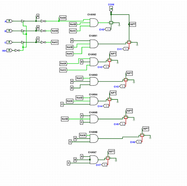
I started emulating some CMOS IC's I used frequently, such as the CD4051; I have read the datasheet and have successfully designed 405x's in working circuits, but, how do these IC's really work?  

My 4051 Sim. There is a mux simulator tool in L-E; I could have used that for the 4051; instead as an exercise I primarily used AND gates.

Running some test signals through this "IC" it seems to work. Off to a good start....

New Idea--Transmission Gates

OK with some understanding of basic gates (a good summary is here) I felt some improvement--from newbie to "a bit beyond Newbie" perhaps?

What next? 

Again: anything.

"Transmission gates" were new to me. 

They are sort of like VCA's, FETs or BJT transistors when used as a switch--in a transmission gate, if control data goes North to South, logic can flow East to West.  

I hadn't heard of these before, but digging into datasheets, yes, they are present by the bushel basket in many of our beloved CMOS IC's...for instance on the 4014 datasheet--i.e., below, circled in red:


That's a transmission gate.  

Here's a transmission gate in L-E:


Emulating the 4014 datasheet fragment somewhat:

Clock and ClockInv: Feed one side to North, the other side to South. Now, on every positive clock you can pass data through the gate. On negative clock you can't.  

Datasheet Limitations?

Next: I went through more CMOS IC datasheets--most have a logic diagram--to get more IC CMOS favorites working in L-E.  

Bad news--I found that simulating the datasheet's logic diagram sometimes and perhaps often (?) didn't work.  

Apparently whoever drew up the diagram for one logic sheet or another just got the damn thing wrong--some of the diagrams had serious mistakes and/or omissions; not sure if this was intentional--protecting intellectual property, or perhaps multinational IC manufacturers getting lazy?

Regardless, in some cases I had to modify the datasheet's diagrams or start from scratch to get the IC simulation to work. 

You can look at what I've "finished" on github, here--please fork 'em and improve 'em. 

CPU/MPU is Next....

With some CMOS IC's under by belt--next question--could I simulate a basic 8- or 16-bit CPU of my own design?

Having watched all one thousand of  Ben Eater's awesome Vids  I felt I had a basic idea of how CPU's work--registers, ALU, busses, memory, mux's etc., so instead of planning I dug in and started simulating. 

Bad idea?

During my logic simulation equivalent of the Dead's space jams I realized I wasn't simulating a CPU--I was trying to make an entire computer:


Jerry's Kids! What I created as of 2-20-24. "CharPU" uses 16 12-bit opcodes, supports (so far) a Program Counter, one 16 bit register, 256 bytes of 8 bit ROM. Works--but the simulation has a long way to go....

To get this working I needed a "counter within a counter"--to step through, say, the 5 or 6 clock cycles needed to write from ROM to a register.  For this I simulated a ring counter....using simulated D flip-flops.  

Ring Counter simulation. The inverted feedback path creates a "Johnson Counter".  

At this point I started to see some of the limits of L-E:

  • I couldn't assign pins to be an Input and Output at the same time--see the discussion here. Which means (as I see it): I couldn't easily create a bidirectional data and address bus. Apparently this not changing any time soon. This meant I needed a data bus for input abd aniother for output. Extra wiring, but this remains better than breadboarding but to me.
In L-E you cannot have bi-direction busses....
  • Don't expect a lot of I/O from the real world into your SIM. Apparently you can enhance your Sim using TCL ("tickle") but I don't have time to learn a new high level language....it would be nice if the serial I/O could attach to one the host's PC "real" serial ports, but that's wishful thinking. There is a keyboard simation tied to the host PC's keyboard and a behind glass TTY display. The list of improvements slated for L-E is huge (here) and with everyone clamoring to get more FPGA's working with L-E I doubt anything a newbie audio guy like me wants to see some UART enhancement will get much traction....but still, serial port I/O would be cool, hook your L-E sim to an arduino!
  • My big battle has been staying organized. L-E allows for the creation of subcircuits and importing preexisting Logisim libraries, but still, I found keeping everything straight, especially when things got a bit complex, became a major challenge--even with the primitive CPU above I struggled with things like consistent tunnel names, zooming in and out, and making things easy to follow and understand.
  • When viewing projects, how come there is a vertical scroll in L-E but a not horizontal one? 


Conclusions--is a life of logic for me?

Maybe. On a different planet/different reality/different universe I could be working for Intel, laying out CPU logic and being happy (and not showering, ever).

Probably.  

Coda...I spent a lot of time with L-E for a few evenings and an entire weekend and it really played hell with my OCD. Little eating; little sleeping, zero breathing fumes, just me and my PC. Something about the reward of seeing the little red lines (doesn't work) in L-E turn green (works) was appealing. 

My psychiatrist wife is worried--L-E and a life of logic could be dangerous for me. We will see.


Anything to Clock Subcircuit

Readers:  If you want to build the project featured in today's post, please go to  PCBWAY's  Community pages --a gerber ready to dow...