Still can't solve that one!
Update! I am using Front Panel Express as well for this--see the post here, it's about $40-50 USD for a single 1-U Frac, that's not what I call low cost, but they make great stuff....
Instead, I have been using a water slide decal process to get me close to silk screen type front panel finishes using something a decal process called "Lazertran".
That's what this post is about.
No, I don't work for these guys. This isn't an ad or promotion. This is however the best way to make low cost one-off front panels that I have found to date. it's $1-$2-$3 USD per panel, pretty affordable.
Still with me?
Next, go out and get this stuff: "Lazertran." You can find it online direct from the manufacturer, also at Blick Art, Amazon, and several other online suppliers. Your local art store may also have it, or maybe can order it for you. As of 12-16-19, with tax and shipping it's about $3USD per sheet.
There is one Lazertran version for laser printer and another for inkjet. Before you Begin! Make sure you have the right printer. There is a list of printers that work on the Lazertran website in the faq section, go here. Hewlett Packard B+W printers (which is what I have) supposedly all work; mine does. I have also read (here) that older Lasers work better than newer ones.
I set my HP 402DW to "heavy paper 130g" so you set up the printer to use card stock; your printer might be different. Lazertran is a bit on the thick side so set your printer accordingly.
I only have tried the process here with the laser version. You can get legal sized sheets or 11 x 17 but here I use 8.5 x 11. I'm interested in knowing if the inkjet material works the same way as described below, if you know I'd be grateful for comments.
Before we go on: the required safety stuff. Please be safe! This process involves putting paper and metal into an oven and cooking it for a few hours. You have to be sensible or you wouldn't survive a week of DIY.....So please, don't be a bozo about this--be careful while handling hot materials, you could burn yourself.

In addition to staying safe, you will also need:
- The metal front panel you want to use, ready to go. If you've painted your metal panel, make sure it will withstand a 250+ F degree oven bake. So, high temperature paints, like those used for car engines, are best. I leave figuring out the right kind of paint to you.
- You'll need an oven that goes to 300-350 degrees F. Most of us have those, or use mom's? Whatever. I imagine toaster ovens will do as long as you can control the temperature.
- Scissors to cut out the decal.
- Computer software to design, modify and flip your decal--Adobe Illustrator is what I use but there are lots of programs for two-dimensional artwork.
- Tongs or BBQ implements to handle your panel when it's hot.
- Paper towel for smoothing out tiny bubbles
- 800 to 2000+ grit wet/dry sandpaper.
One more thing: all the temperatures in this post use the Fahrenheit standard. I know it's downright colonial for me to do that, many of you use Celsius, and most of the time I try not to be a stupid American who thinks the world only exists from Hawaii to New York. I didn't want to constantly post 2 numbers. If needed Here is a good site to translate between the 2 standards.
Prepare your metal work. For Lazertran decals to look decent, your front panel has to be extremely smooth--the decal will tear and hang up on any burrs or rough edges, form bubbles over oil and dirt, and generally look crappy. I thoroughly wash the panel with dish soap, then sand it with 800 grit wet and dry sandpaper, then a 1200 grit sanding pad then wash it again.
Next this may be obvious, but: take careful measurements of your cleaned up panel. If you mess up your measurements you will have printed a $2-3USD Lazertran decal that won't fit your panel, and we don't want that.
If you really don't want to measure things: I have used a Ricoh flatbed scanner to scan a 1:1 image of the front panel(s) in question; then used the PDF output from the scanner as a background in Adobe Photoshop. Before printing I hide the background layer. As long as the original scan is really 1:1, this will work.
Another way: I first draw the front panel in a CAD program (Eagle in my case) to create a down-to-the-millimeter drawing of anything that needs panel art. Save it as PDF or PNG and then use that as the background in Illustrator or whatever graphics program you use.
 |
| Eagle BRD file of a Fracrack 2u panel |
As long as the elements you see in the background are holes, drills, dimension layer outlines, and mills, they won't show up in the final panel, but can be used to design and align the decal.
About color decals: If you are doing a color panel you're in territory unfamiliar to me, I only do B&W, but keep in mind that almost all inkjets can't print white and I don't see that Lazertran is supported for most or all color laser printers. B&W printers assume the background is white and treat white artwork as clear so it can "show through".
I imagine from model making that CMYK colors may appear a bit faded or washed out so flat white paint on the panel before decaling may help. Just a guess.
ENOUGH ALREADY! LET'S MAKE A DECAL!!!!
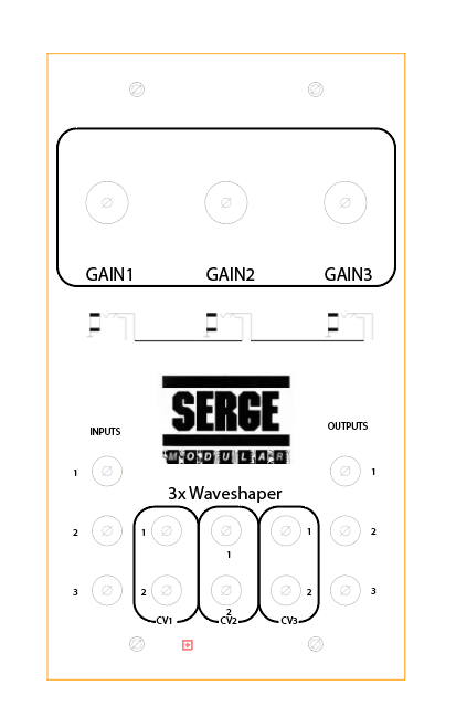
For this tutorial I am fabbing a new one-off panel for a Triple Moog-like VCA clone for which I did a PCB board design, as well as the GCS/EFM/everyone-else Norton 3900 amp based Serge Waveshaper (hence the Serge logos--give 'em credit where it's due--this is a really cool bit of electrical engineering on Serge Tcherepnin's part--you can get details, boards, gerbers etc. for it everywhere, my version is here....
Here's what I ended up with in Illustrator for the Serge module:
Before printing to your Lazertran decal paper, check your printer settings, print out a 1:1 of your artwork, and lay it over the panel to see if everything lines up--you want to do this with normal paper before committing to Lazertran.
Here I've done that with cutouts of standard 8.5 x 11" paper--yep looks OK.

Now go back to your art program, select all the elements in your design and flip things, so it's 180 degrees flipped along the Y axis, like this:

Save the flipped file--we are going to need to print the flipped decal image to Lazertran.
OK, here's a semi hidden secret. You have to BAKE THE DICKENS out of the Lazertran sheet before you take the decal off the backing. Otherwise your decal will bubble during the baking process.
OK, here's a semi hidden secret. You have to BAKE THE DICKENS out of the Lazertran sheet before you take the decal off the backing. Otherwise your decal will bubble during the baking process.
The Lazertran docs say to use a hair dryer, but I use my oven as I've had better results. For this pre-bake-your-decal-sheet process, preheat your oven to 225 degrees F. and then put in the decal for about 6 minutes.
Stink it! As the decal bakes you may smell a gross plastic burning smell. Sorry. And when you take out the decal paper it will look like you tried to BBQ it:
Update: I have gone back to using a heat gun for this. Specifically I am using my hot rework station to bake the decal vs. the using the oven; 3 minutes of blowing the rework nozzle at the decal at 475 degrees seems to do the trick. Probably not what Sparkfun thought of when they put the HAR device on the market?
 |
| Charred Lazertran. Mmm Mmm stinky! |
The good news is--I learned this by trail and success??--the decal will still look OK even though the backing paper got charred. But you can over bake the sheet....then the decal won't come off, so keep checking on your decal during this pre-bake. I have best results when the backing paper is charred to about the point you see in the photo above.
Next, cut out the decal along the panel lines:

if you can, cut out each drill a bit larger than needed (say 100-200 mils)--you will get less bubbles if you lay decals down on flat continuous metalwork vs. having them covering up drills.
Then soak each decal in warm tap water for about a minute--less if you can. Warning: Soak for as short a time as you can; if you soak the decal too long the decal may start to disintegrate. I have seen this on occasion, but other times I have left the decal in the water for 5 minutes without issue. No idea why.
UPDATE: I finally figured out what the issue is with disintegration!
Since about mid 2019 Lazertran put a protective opaque coating over the "decal side" of their decal paper. You need to peel off before running it through your printer. I was having about 30% failure rates with disintegration and I couldn't figure out why.
After looking at the failed sheets under a microscope I discovered removing the opaque protective sheet was also removing the decal material itself. The two look alike so it's hard to tell! So: Be super careful when removing this protective sheet.
The decal material has a slightly matte/bumpy look when you first peel of the protective layer, but becomes shiny after the "heat the decal" process described above. If the decal doesn't get shiny when you heat it up you probably removed the plastic decal material by mistake; and your decal will be butt and disintegrate. Face!.

I didn't get a photo of this, but apply the flipped decal face down to the front panel by sliding it off the backing and onto your front panel.
Line it up carefully.....
Now you've got to get rid of the air bubbles that invariably live under the decal you just applied.
I have tried all different ways to "de-bubble" but the best way, the way I always come back to, is use my fingers to get the big bubbles out, then gently (!!) use a credit card edge to wisk away all the smaller bubbles. You will probably have to re-position as you go, that's not a problem, be gentle so you don't tear the decal.
Again no photo for this--I was too busy trying to not ruin the decal and get rid of all the bubbles. But with a gentle touch it's not a problem.
Hold the panel up to a light and see if you can see bubbles under the decal. If you can still see bubbles, repeat the process.
Last step before the bake, take a napkin or paper towel and carefully dab off whatever water remains on your panel. Then check for air bubbles again.
Once you're bubble free it's time to bake the decal onto the panel.
ON TO THE PREBAKE--GET THEM BUBBLES TO BUBBLE, RAWHIDE!
Preheat a cookie sheet to about 225 degrees and before the initial bake, remove the sheet and put it on your counter. Then, put the metal panel w/ decal face up directly on the sheet. I have seen some bubbles I missed immediately bubble up at this point. They can be pushed back down with a quick stab with your fingers. Yes, a 225 degree metal cookie pan is hot , so be careful, but this "prebake, prebubble" step is completely essential.
BAKE THE DECAL AND METAL!
With the decal now fully debubbled, set you oven to 170 F and put the decal in there for 2 minutes.
Important: After 2 minutes remove your cookie sheet, and check the panel and make sure bubbles haven't formed. If you have bubbles at this point you can quickly touch them to flatten the bubbles or pop bubbles with a pin, thus repeating what you did in the "Prebake."
After about 10-15 minutes the big ones are with you to stay.....so set your timer and do this check.

(I have done Lazertran bakes in a pan, on tinfoil and on a cookie sheet--after trying different things, baking on cookie sheet seems to work best....)
After the two minute check, try another check at 10 minutes; after that you're past the bubble popping stage.
Keep the oven at 170 F for an hour (if you are impatient, half hour will do, but the more time you bake the better the decal looks at end), then 190 F for an hour, then 220 F for an hour. OK, 250 F for an hour, finally 275 F for an hour.
Don't go over 275--the decal might burn if you do. Not 100% sure about this--I have gone to 350 F without issues, but other times going above 275 will make the decal turn brown.
When all this is done, remove the cookie sheet from the oven, and let it cool. Next remove the panel from the sheet with your tongs. After your 4+ hour bake, if everything went OK, you end up with a pretty darn good looking panel, not quite pro silk screen looking, maybe a few blemishes here and there, but close.....with some practice you can get really close.
 |
| Look Ma! No Photoshopping!....if you are careful with lazertran the results can be very clean. |
And after a full bake if all went well, the finish is really baked on--I have had difficulty removing the decal with 500 grit sandpaper. Yeah!
For clean up, you may need to take an X-acto blade and get rid of any remaining decal material that's sitting over a drill, outline, or cutout. But for me after a few hours most of the decal that went over holes and milling has baked off.
And....if you did end up with bubbles, you may be able to sand them off. If needed, I use 800/1000/1200 grid wet n' dry sandpaper to gently sand the panel to give it a more uniform look. Don't be too rough--especially with the 800--but if you baked the decal on for hours it should withstand a lot of abuse.
I have experimented with clear coating, but am not sure that improves things any.
Here's what I ended up with while doing this blog post:

OK that looks pretty good I think!
We're now ready to finish things. Bolt on the PCB, mount pots, knobs, etc.
Here is how my Serge Waveshaper clone looked when I was done.

Not too shabby? You can get very fine details out of this process--the "1", "2", "3" by the jacks is 6 point font and is fully legible, and the "normals" illustration below the gain knobs is even smaller but came out just fine. You get the idea.
One more hint:
If you're in the process of fabbing your panel, you might try experimenting with baking on the decal following the process above and then drilling out remaining holes and mill work.
As long as you drill and mill carefully--a skittering drill bit will tear the decal, screw up your panel and possibly injure you--this works better than drilling/milling then applying Lazertran. You can add x marks to your decal where you need to drill....this helps with panel symmetry and drill placement.
OK that's it for now, give it a try and let me know what you think. I am always working on improving this process.