Hello again: if you've been following the last few posts you see that I am trying to use Arduino's IDE a lot less, and learning to program microcontrollers like the Atmel 328P using
"Embedded C", as opposed to the Arduino Sketch language.
I've had some success, such as using C to create an LFO prototype...read about first steps for the DLFO project here. It works on the bench. Update 5-1-21 the whole damn Digital LFO--dev board discussed below, buffer board for incoming CV, switch debouncing that toggles waveform select, LEDs to show which waveform you're using etc etc. works!! I am happy; post is here.
Question: if I stop using Arduino's IDE, can I stop using their hardware as well?
Why/Why not?
Turns out it's pretty easy to roll your own simple AVR based dev board. Using bits of the Arduino Uno R3 schematic, a few examples found online (eg: here), and a few Atmel PDFs (the one here for instance--very useful reference document) I came up with a minimal parts count AVR 328 PCB for future projects.
If you want to build one of these yourself, you can get the Eagle files (the free version of Eagle should be able to load these files), gerbers, and more, from my github (go here). It's also available from PCBWAY's Project Pages (here).
Schematic and board look like this:
But does it work?
Programming is done with an Atmel ICE; the IDE used for writing the blink code is Atmel Studio 7, as in the previous posts. Since this board doesn't have a serial interface chip, and Arduino IDE works over serial (and requires a slightly different reset pin decoupling setup), it won't work for that; it's for embedded C developers, mainly.
Let's send this dev board's gerbers off to China....I like PCBWAY....wow that was fast, they are back.
Let's stuff the board:
I used a chunky TO-200 regulator for this test, if your application requires less current, you can use a TO92 regulator. The board supports both footprints....Don't use both at the same time....
On the bench, connected to power and so on, it looks like this:
The power etc. checks OK.
Next, with a brand new 328 chip popped in we can upload this simple blink C program to test:
#include <avr/io.h>
#include <stdio.h>
void Delay(void);
int main(void)
{
//DDRB = 0x20; // set bit 5 of DDR register which makes PB5 an output
DDRB = 0x02; // use PB1
while(1)
{
PORTB = 0xFF; // switch LED on
Delay();
PORTB = 0x00; // switch LED off
Delay();
}
}
void Delay(void)
{
volatile unsigned long count = 15000;
while (count--);
}
And...nothing. Huh? This is a really simple design, why won't this work?
It took me about 5 minutes to figure this out.
The Atmel ICE's ICSP connector is pinned like this:
...but when designing the ICE connector no one at Amtel (?) marked where pin one is. Or if you are looking at the connector from the pins side (6 females) or the back. Turns out I had the connector upside down!
On my board, the MISO pin goes to the top left. So the tab you see on the connector faces upwards.
After this fix, the MCU is now seen by the ICE programmer and we can upload code. yeh!
Let's blink.....
Cool! To fully take advantage of the 16Mhz crystal you need to change a fuse setting...if you do this wrong you can brick your Atmel 328 chip...so be careful.....a video with complete details is here; if you want to use atmel studio's fuse user interface to make this change take a look here.
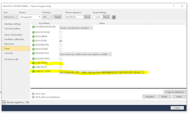
Here are the fuse settings I usually use--what is hi-lighted below is not default for a new, "non-Arduinoized 328 microcontroller. You will have to change these settings, say a prayer, hold your breath and click on PROGRAM.
Again: if you screw up the fuse settings you may brick your 328 IC, so be careful!!!!
Settings I used for this project: 16mhz clock, 65ms start up, and no divide clock by 8.
Note that for Atmel fuse settings "0" is on and "1" is off--nice!
IMPORTANT: Check that the 16Mhz xtal is working before changing the LOW.SUT.CKSEL fuse setting or your entire board may not work as the clock speed for the board, and what the processor expects, don't match.
Wow--ok, it seems to work.
Good enough for now--"not much time for blogging + too much work to do...."
Next up, I'll see if I can make the recently "coded at the bench" DLFO (again, post for initial software DLFO build is here) work with this development board. I created a 2nd PCB for the DLFO to accommodate its CV buffers and whatnot and should have that back soon.
Update: DLFO is done and works--post is here.
Update: 8-6-21 I need to do another run of the minimialist boards here; when I do the PB1 LED anode should be wired to 5V and cathode to R3 (then to a digital pin on the Atmel MCU). This will make the board more current efficient if you're using the on board LED for something. I also want to flip the ICSP connector 180 degrees and make a few other minor changes.
That post is coming as well.
Stay tuned and don't breathe the fumes!


