
I looked around and found a bunch on Ebay that were quite expensive, but I managed to spouse up some New Old Stock National Semiconductor NSA1166 seven segment displays--6 bubbles for numbers + decimals--at Jameco, for less than $3 each--cheap.

Those showed up fast!
OK first thing I did was dig into the NSA1166 datasheet, which seems a bit, well, brief?--you can see it here.
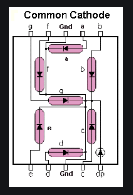
I knew zilch, and I mean zilch, about 7 segment LED displays, they had never crossed my path before. Wait, where is VCC and GND? Turns out: doesn't work that way. You get a configuration like the one below (without the current limiting resistors). This is called, for obvious reasons, "Common Cathode"--in this case 8 LED anodes per bubble, but one shared cathode for all of 'em:

That means: current sourced to A1-A8 light up segments of the LEDs in a single bubble, which are laid out like this:
The idea is that an MPU (Arduino for instance--could also be a driver chip, transistors, electro-cups and string, or whatever) sends current to one set of LEDs, that is, one bubble, say LEDs "B" and "C" in the leftmost bubble, to make the number "1", then the MPU moves on to the next bubble--fast. The persistence of vision in your eye make each of the six bubbles look like they are always on even though they aren't. Marvey. Turn on the Bubble Machine!!
OK with that super basic knowledge under my belt, it was time to see if anyone had already written up an easy way to hook 7 segment displays up to Arduino type MPUs. Why reinvent the wheel?
Answer: yes and yes and yes--this has been done many times before in Arduinoland....
But so far no perfect fit I could find, for me anyway.
The post here is a very cool implementation but appears to work with 3 different Arduinos, none of which I had.
But so far no perfect fit I could find, for me anyway.
The post here is a very cool implementation but appears to work with 3 different Arduinos, none of which I had.
Or the one here, but it uses HP NOS bubbles which seem expensive and hard to find.
Or...well....there are tons of other designs out there, but since I have lots of time on my hands, had never touched a seven segment display before, and needed a project to waste time on, I conjured up my best Nixon--I'll erase it myself!
Some design goals:
- My implementation must work with a wide range of Arduinos and other Arduino-like MPUs
- It had to work with the NSA1166 since that's all I had in terms of 7-seg displays
- The finished design had to be as modular (i.e., reusable in other projects) as possible.
- It can't flicker, stutter, or looks obvius crap-like
- It can't show the wrong numbers (duh)
- A 3 digit number is shown from the far right bubble; and in that case, the left 3 digits must blanked--same idea for any "blank" needed. So no 000333. I want to just see 333.
- The display had to be reasonably fast to respond to new values at input--10ms?
- It has to take up as few pins as possible on the Arduino (since I might want to drive this from an ATTINY85 someday, or just have other things I want to use the Arduino for in addition to this display?).
- OK to use external jellybean parts, but let's keep it reasonable.
OK, let's motorize this pursuit.....
I already had an UNO (easy to develop with) about 3 clono nanos (Ditto) and maybe 5 clono Pro Minis in my junk box. The latter meant finding, untangling, and then hooking up the tiny USB to Serial adapter for programming;
Whatever, I developed with the trusty UNO. it has enough I/O pins for the bubble display but then I'd be out of pins for anything else fun--so let's use a shift register such as the venerable 74HC595 to free up pins; I used two 595 breakout boards from Sparkfun for my POC:

No Shift, Sherlock! There is a ton of information about using shift registers with Arduinos on Youtube (here and here for instance) as well as the forums etc. (post here was very useful for this project).
I had issues with the fact that pins in 595-land aren't always called the same thing from chip to document to breakout board to forum page...which got me feeling stupid and frustrated from time to time. I'll live.
Here is the "595 Cheat sheet" I came up:
I had issues with the fact that pins in 595-land aren't always called the same thing from chip to document to breakout board to forum page...which got me feeling stupid and frustrated from time to time. I'll live.
Here is the "595 Cheat sheet" I came up:
HOW IT WORKS:
- Bits of data--two bytes total in our case, come in the SERIAL in port.
- Each HIGH on Serial Clock shifts everything over one to the right. The arduino "shiftOut()" function handles that and the timing. Yeh!
- Each LATCH going high says "we are done with the bullshift, present everything to the world, ready to use".
- You can put x number of 595s in series and it all works; I used 2x 595s for this, but you don't have to stop there; you can get as many digital I/O pins as you need by putting more registers in series, flowing your SER bits through all of them, then LATCHing all of it when you're ready to go. And through it all--even if you have 10 of the damn things lined up, that's 80 I/O pins, you'll never consume more than than 3 Arduino digital pins for the whole enchilada. Obviously this is a very useful IC for what we do.
WHAT THE 595's PINS DO:
- Q0-Q7 outputs. What we want to use to drive our bubble display's LEDs. These pins can source or sink current and light up the LEDs (with current limiting resistors); I didn't find anything definitive about the current limits for the NS1166 in the NS datasheet--whatever; 5V with 330ohm-ish resistors did the trick, and 3V worked w 330ohm R's as well albeit a bit dimmer. No smoke!
- DS-Serial data. Seen it as "SER" on some CMOS data sheets, and called "SER IN" on Sparkfun breakout. Your serial data--the 8 on/offs you want to blow into the shift register--goes in here.
- OE--output enable. Active Low. Called /OE on the Sparkfun breakout board. We want our outputs enabled eh? Well Yes we do or else nothing happens. So, tie this to ground.
- SH_CP is clock pin. Each time the clock goes low to high, the bits shift in the device one to the right. Called "CLOCK" on Sparkfun board.
- MR--master reset. Active low. This clears everything in the register, and we don't want to clear everything ever for this application, so tie it to 5V. Called /RESET on the Sparkfun.
- ST_CP "Latch" pin. When that goes high, everything in the shift register is presented to the outside world. Called L_CLOCK on the Sparkfun device.
- Q7' (Q7 prime) is SER_OUT on the Sparkfun. Use to daisy chain your 595s, so serial going into one IC can feed as many 595s in series as you need for your project. I've seen this called "QH" or "QH*" on some chips and data sheets.
SHUT UP AND BUILD THE THING ALREADY!
OK dammit!
I ended up bread boarding this:
I ended up bread boarding this:

Some bench photos:
 |
| I had to modify a cheap breadboard to accommodate the 595's. Sparkfun needed to make these breakout boards about 200mils wider! |
 |
| I added extra LEDs in parallel with the bubbles to better see what was going on with the 595s. |
 |
| Final POC was to have the pot make the display read from 0-1023 based on the pot's wiper position. Works! No flicker! |
OK how about the code? Here is what I was using to get the pot to go--I wrote other variations to try out other things, comment if anyone wants to see those.
This wasn't too hard--it took a couple of evenings. I got stuck for maybe an hour on one strange thing--the bubbles wouldn't work reliably if I was using Serial.write to debug. Commenting the serial stuff out, the bubbles worked again. So I was introducing a bug by debugging? A pest, but yes.
This wasn't too hard--it took a couple of evenings. I got stuck for maybe an hour on one strange thing--the bubbles wouldn't work reliably if I was using Serial.write to debug. Commenting the serial stuff out, the bubbles worked again. So I was introducing a bug by debugging? A pest, but yes.
A few >'s instead needed to be <' s but overall, not bad at all.
//////////******************************
long testnumber = 0;
//testnumber is what I want to show up on the NSA1166.
//you have to use long. int only goes to 32000 or something close!
//////////******************************
unsigned long startMillis; //start millis timer
unsigned long currentMillis;
const unsigned long period = 10;
//each item in the array below ground a given pin of a 595, so the Bubble can display.
int mybubble[] = {124,188,220,236,244,248};
int c = 0; /* used to hold number of elements in the array */
long n;
int p = 0; // counter for filling array with elements.
int numberArray[6];
//this holds each value of number we are trying to display
// bubble zero is leftmost bubble!
long bubble5 = 0;
long bubble4 = 0;
long bubble3 = 0;
long bubble2 = 0;
long bubble1 = 0;
long bubble0 = 0;
//pins used to feed shift regs
//Pin connected to ST_CP of 74HC595
int latchPin = 8;
//Pin connected to SH_CP of 74HC595
int clockPin = 12;
////Pin connected to DS of 74HC595
int dataPin = 11;
//pot wiper connected to A0. gnd AND 5V for the rest
int pot = A0;
void setup() {
// put your setup code here, to run once:
//set pins to output so you can control the shift register
pinMode(latchPin, OUTPUT);
pinMode(clockPin, OUTPUT);
pinMode(dataPin, OUTPUT);
// debug using serial
//Serial.begin(9600);
// BE CAREFUL serial stuff can step on Bubble display and make it mysteriously not work.
// initialize array
numberArray[0] = 0;
numberArray[1] = 0;
numberArray[2] = 0;
numberArray[3] = 0;
numberArray[4] = 0;
numberArray[5] = 0;
}
void loop()
{
//do a analog read every 10ms
currentMillis = millis();
if (currentMillis - startMillis >= period) //test whether the period has elapsed
{
testnumber = analogRead(pot);
startMillis = currentMillis;
}
c = 0;
// turn that number into an array. Note: ARRAY is backwards!
//first we need to determine how many digits the number in ques\ton has. We need that to send //blanks out later
n = testnumber;
while (n != 0)
{
n /= 10;
c++;
}
/* Serial.println("testnumber variable value is: ");
Serial.println(testnumber);
Serial.println("length of array is: ");
Serial.println(c);
*/
/////////////////
n = testnumber;
p = 5;
//now fill an array with each digit.
while ((p > -1) && (n != 0))
{
numberArray[p] = n % 10;
n /= 10;
/*
Serial.print("----------");
Serial.println("We are seeing output of array value");
Serial.println(p);
Serial.println(numberArray[p]);
Serial.println("");
*/
p--;
}
//wanted to time more CRAP then realized it wasn't needed, comment that!
//Leaving it here in case I remember what I was thinking.
////currentMillis = millis();
//if (currentMillis - startMillis >= period) //test whether the period has elapsed
//{
//startMillis = currentMillis; //update current millis.
/////////////////////////////////////////////////
/////////////////////////////////////////////////
//YEH next part can be simplified and made into a single function.
//I am too lazy to do this. you do it!
//AND--I don't accommodate decimal points at all.
//Again I am too lazy.....
////////////////////////////////////////////
bubble5 = getbyte(numberArray[5]);
//write to shift reg. rightmost digit.
// take the latchPin low so
// the LEDs don't change while you're sending in bits:
digitalWrite(latchPin, LOW);
// next line puts numeric data onto shift register
shiftOut(dataPin, clockPin, LSBFIRST, bubble5);
// then pick which bubble to impact
shiftOut(dataPin, clockPin, LSBFIRST, mybubble[5]);
//take the latch pin high so the LEDs will light up:
digitalWrite(latchPin, HIGH);
//write to shift reg digit. 2nd from right
if (c < 2)
{
bubble4 = 0;
}
else
{
bubble4 = getbyte(numberArray[4]);
}
// take the latchPin low so
// the LEDs don't change while you're sending in bits:
digitalWrite(latchPin, LOW);
// next line puts numeric data onto shift register
shiftOut(dataPin, clockPin, LSBFIRST, bubble4);
// then pick which bubble to impact
shiftOut(dataPin, clockPin, LSBFIRST, mybubble[4]);
//take the latch pin high so the LEDs will light up:
digitalWrite(latchPin, HIGH);
//write to shift reg digit. 3rd from right
if (c < 3)
{
bubble3 = 0;
}
else
{
bubble3 = getbyte(numberArray[3]);
}
// take the latchPin low so
// the LEDs don't change while you're sending in bits:
digitalWrite(latchPin, LOW);
// next line puts numeric data onto shift register
shiftOut(dataPin, clockPin, LSBFIRST, bubble3);
// then pick which bubble to impact
shiftOut(dataPin, clockPin, LSBFIRST, mybubble[3]);
//take the latch pin high so the LEDs will light up:
digitalWrite(latchPin, HIGH);
//write to shift reg digit. 4th from right
if (c < 4)
{
bubble2 = 0;
}
else
{
bubble2 = getbyte(numberArray[2]);
}
// take the latchPin low so
// the LEDs don't change while you're sending in bits:
digitalWrite(latchPin, LOW);
// next line puts numeric data onto shift register
shiftOut(dataPin, clockPin, LSBFIRST, bubble2);
// then pick which bubble to impact
shiftOut(dataPin, clockPin, LSBFIRST, mybubble[2]);
//take the latch pin high so the LEDs will light up:
digitalWrite(latchPin, HIGH);
//write to shift reg digit. 5th from right
if (c < 5)
{
bubble1 = 0;
}
else
{
bubble1 = getbyte(numberArray[1]);
}
// take the latchPin low so
// the LEDs don't change while you're sending in bits:
digitalWrite(latchPin, LOW);
// next line puts numeric data onto shift register
shiftOut(dataPin, clockPin, LSBFIRST, bubble1);
// then pick which bubble to impact
shiftOut(dataPin, clockPin, LSBFIRST, mybubble[1]);
//take the latch pin high so the LEDs will light up:
digitalWrite(latchPin, HIGH);
//write to shift reg digit. leftmost
if (c < 6)
{
bubble0 = 0;
}
else
{
bubble0 = getbyte(numberArray[0]);
}
// take the latchPin low so
// the LEDs don't change while you're sending in bits:
digitalWrite(latchPin, LOW);
// next line puts numeric data onto shift register
shiftOut(dataPin, clockPin, LSBFIRST, bubble0);
// then pick which bubble to impact
shiftOut(dataPin, clockPin, LSBFIRST, mybubble[0]);
//take the latch pin high so the LEDs will light up:
digitalWrite(latchPin, HIGH);
} // end main loop
//shiftOUT does not seem to accommodate bxxxxxxx typle format?
//whatever, I am using decimal values for this.
byte getbyte(long x)
{
int a;
if (x == 0)
{
a = 252; //11111100
return a;
}
if (x == 1)
{
a = 96; //011000000
return a;
}
if (x == 2)
{
a = 218; //11011010
return a;
}
if (x == 3)
{
a = 242; //11110010
return a;
}
if (x == 4)
{
a = 102; //01100110
return a;
}
if (x == 5)
{
a = 182; //10110110
return a;
}
if (x == 6)
{
a = 190 ; //10111110
return a;
}
if (x == 7)
{
a = 224; //11100000
return a;
}
if (x == 8)
{
a = 254 ; //11111110
return a;
}
if (x == 9)
{
a = 230 ; //11100110
return a;
}
}
///////////////////////////////////////////////
OK so this all works! What is next?
It would be cool to use some pins on the Arduino (Something w/ a smaller form factor than an uno) to make this into an I2C slave device. Then, I could drive the NSA1166 with I2C and never have to think very hard about adding bubble displays to my projects again. Update: I2C control of the NSA1166 works. Part II, where I get I2C working with 32 bit datagrams--needed for a 6 digit display, is here, part III, where I get it all working with I2C, is here.
It would be cool to use some pins on the Arduino (Something w/ a smaller form factor than an uno) to make this into an I2C slave device. Then, I could drive the NSA1166 with I2C and never have to think very hard about adding bubble displays to my projects again. Update: I2C control of the NSA1166 works. Part II, where I get I2C working with 32 bit datagrams--needed for a 6 digit display, is here, part III, where I get it all working with I2C, is here.
Also, would be nice to get decimals going, but I don't have an immediate need for that, so for now, wah-wah.
That's it, no smoke, no fumes, bubble up the covid and leave it behind!
That's it, no smoke, no fumes, bubble up the covid and leave it behind!


No comments:
Post a Comment