 |
| Update 10-25-20: Why ever make one when you can make 3? Siff units add voltage control of time. Finished-all of them work--nasa, we have echo. |
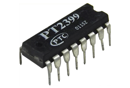
These 3 modules are based on the extremely popular PT2399 audio Delay IC, which as I understand it was originally manufactured for the Karaoke market.
The chip is super inexpensive--I got 20 from Amazon recently for about $1 each USD. When do you see that sort of price for specialized audio IC's?
There are quite 2399 kits you can buy: MFOS, Befaco, and more. But audio kits built "stock", to me are like building a puzzle: great way to pass the time but what are you learning, really?
So I started down the path of coming up with my own echo unit based on this chip. First, the usual web research: The defacto "how this chip really works" page is from Electrosmash, here. Somewhat crappy datasheet for PT2399 is here, and diyaudiocircuits has a good page for PT2399, here. A good E-M page for 2399 is here. Trying to get longer delays out of it? I haven't tried it yet, but, go here.
To get started, I found a github webpage (here), where the author, Joe Beuckman lays out a design very similar to the PT2399 datasheet's and posts it in Eagle format. And it's single sided. Great starting point; let's build it:
 |
| The PT2399 datasheet layout, in Eagle format |
Back! Let's build:
Here's the PCB:
The circuit needs 5V power and my Frac rig is +/15V, so I used the 15V-5V linear DC converter from a previous Arduino project, get that from my website here.
PCB front panel for test is left over from the noise! project.....
Bench testing, I found the input level to be a bit weak so I added a +6db buffer at input, simple non- inverting buffer circuit; get that on my website here. I used 2x 100K resistors for R1/R2 there, to get the 6db gain. Also, the 18K resistor R7 in the feedback loop seemed a bit high. I tried lower values (10K is better) but settled on a B25K pot wired in parallel with the feedback resistor, giving me redundant control between the existing "feedback" pot and this new pot, which I called "loop". OK, between the two pots I can now get endless feedback.
Then it was a matter of screwing it all together with 4x40 hardware. Easy.
Here's the read-to-test module, ready to go in the rack. Obviously this is a temporary front , but before I start adding VC, modulation, wet/dry and a whole bunch of other enhancements I have something to try out that gives me basic echo. And best of all, it sounds, to my ears anyway, surprisingly good--tops out at about 300ms per repeat, good for a $1USD audio chip. For 1000ms echos, or chorus, or flanging, or whatever else....you probably can't do any of that easily with the PT2399, but what the PT2399 does it does well.
 |
| Temp front panel--very nice! |
 |
| Original PT2399 echo w/ Mr. Label front panel. Finished! I experimented with "Send and Receive", buffering the feedback loop from PT2399's output to input; so you can plug effects into the effect. Works! Also brought out a buffered "wet only". These mods and everything else are visible in the schematics for the skiff version, view PDFs for that here. |
Next up: I already redesigned this basic PT2399 board to include the power and buffer and extra pot on a single PCB, allowing SKIFF if someone wants that, and will also fit behind a 1u Frac panel or about 6HP Euro. I repeated the buffered send and receive as well as bringing out "wet only". We're off the races on another fun organic audio project.
UPDATE 10-25-20: Skiff/REV2 units are done! I made a PCB for the skiff front panel that had some mistakes, so I made a new PCB that fixed them. Besides needing kludge wires, Skiff #1 needed attenuation for VC in, which I added for round 2.
10-31-20 DONE, no more echo please! for eagle files, PDFs etc, go to the web page here.
The two revisions of the jacks board for SKIFF; please enjoy the kludge wires for REV1 on the left.
The "main" board, for the PT2399 etc., worked first time although the TIME pot goes backwards, so CCW is fast delays vs. slow. Whatever, keeps me creative in the studio.
OK that's it for this time, until next time, don't breathe the P(o?)T fumes.


No comments:
Post a Comment