Managed to title this post without using a single word. How that? And: B'Big BoB, Gibb! is a palindrome? Yeh I just knew ya would.
Enough: this is post part 2: how to get started with the FTDI232H breakout board. For this to make sense you'll probably need to skim part I of this post; go here.
 |
| The mighty and very affordable FT232H breakout board. |
This Breakout Board is inexpensive and gets your PC talking GPIO, UART ("serial"), SPI and I2C, as well as other useful protocols, really fast. You need to do some coding however; I used the PYFDTI python module.
Last time we covered GPIO and UART, now let's see some more PY-FTDI programming examples to get SPI and I2C going.
To test I2C I wired the FT232H to an Adafruit 4725 I2C DAC Breakout board to see if I could see voltages on a scope....the MCP4725 (datasheet is here) is an affordable I2C digital to analog converter, and Adafruit's BoB's are always reliable and well documented.
Wire it up like this:
Clip your scope lead to the output of the MCP4725 breakout board.....
Then, run the sample code below on your PC.
To see the output voltages move around, change the values in a.write (bytes) (to 0x00,0x00 for instance, or 0xFF, 0xFF) and re-run the script.
BTW, your MCP4725 may not be set to addr. 0x62 since the board can be configured to operate at different I2C addresses. See the comment "You need 2 byte addr..." in the code example below. You'll need the right I2C address for your 4725 for the code fragment to work.
////////////////////////////////////
from pyftdi.i2c import I2cController
i2c = I2cController()
device = 'ftdi://ftdi:232h:0:1/1'
'''
YOu need 2 byte addr. of your i2c dookie.
use "i2cscan.py" to get the
address of your I2C device.
i2cscan.py is in the "tools" included with
pyftdi
However you need to modify i2cscan.py first.
find this line, then put your URL here:
argparser.add_argument('device', nargs='?', default='[YOUR-FTDI-URL-HERE]'
OK run the i2cscan.py script
output of that program is a grid with a single char, not a value.
Q: what do x and y axis in the grid mean?
A: it indicates the address where it found your I2C device.
to craft hex addr of device it's:0x(column row)
you knew that right?
'''
slave_port = (0x62)
i2c.configure(device)
a = i2c.get_port(slave_port)
#'0x0F,0XFF is full throttle'
#'0x00,0x00 means 0V from DAC out'
a.write([0x01,0xFF])
OK we have DC. But why stop there? Modifying the code slightly produces a crappy ramp wave:
Scope out looks like this:
SPI-ing on the FT232H: ...here's the wiring, for testing we use the FT232H and a Arduino UNO that's set as an SPI slave:
Code for the PC:///////////////////////////
from pyftdi.spi import SpiController
#pinout from H232 for SPI
'''
ad0 SCLK to UNO pin 13
ad1 MOSI to UNO pin 11
ad2 MISO to UNO pin 12
ad3 CS0 to UNO pin 10
ad4 cs1 ... ad7 CS4.
'''
# Instantiate a SPI controller
# We need want to use A*BUS4 for /CS, so at least 2 /CS lines should be
# reserved for SPI, the remaining IO are available as GPIOs.
spi = SpiController(cs_count=2)
device = 'ftdi://ftdi:232h:0:1/1'
# Configure the first interface (IF/1) of the FTDI device as a SPI master
spi.configure(device)
# Get a port to a SPI slave w/ /CS on A*BUS4 and SPI mode 2 @ 10MHz
slave = spi.get_port(cs=1, freq=8E5, mode=1)
qq = bytearray([6,15])
# Synchronous exchange with the remote SPI slave
#write_buf = qq
#read_buf = slave.exchange(write_buf, duplex=False)
slave.exchange(out=qq, readlen=0, start=True, stop=False, duplex=False, droptail=0)
slave.flush() Code for the Uno: /////////////////////////////////
#include<SPI.h>
volatile int i = 0;
byte myArray[2];

void setup()
{
  Serial.begin(9600);
  pinMode(SS, INPUT);
  pinMode(MOSI, OUTPUT);
  pinMode(SCK, INPUT);
  SPCR |= _BV(SPE);
  SPI.attachInterrupt();  //allows SPI interrupt
}

void loop(void)
{
  if (i == 2)
  {
    int x = (int)myArray[0]<<8|(int)myArray[1];
    Serial.print("Received 16-bit data item from Master: ");
    Serial.println(x, HEX);
    i=0;
    Serial.println("=============================================");
  }
}

ISR (SPI_STC_vect)   //Inerrrput routine function
{
  myArray[i] = SPDR;
  i++;
}/////////////////////////////


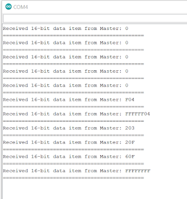
Serial output looks like it's working--yeh baby:
OK enough tests.....Here's a real-world example of the FT232H at work:
I attached an Analog Devices 9833 function generator IC downstream from the FT232H breakout board. The 9833's data sheet is pretty hard to follow I think, but, a good "getting started" page going over the basics is here. And yes, you can get 9833's on an inexpensive breakout board in North America, assuming this Amazon post still works: here.
There is an Arduino library for it, a library for programming the 9833 using C++, and on and on--it's everywhere!! But....we'll use Python.....
Yep, let's make some sine waves using PYFTDI and the FTDI232H:
Wow, that's alotta sinegina....... get all code samples for this post from Github, here. Update 12-31-20 see the post here for another PYFTDI-9833 code example where you can enter in the frequency you want at output.
Enough...back to the day job....I will probably work more with the PYFTDI-9833 Function Generator code and hardware in a future post, even though there are plenty of projects/web sites that already tell you how use the 9833 to make a decent FG. Maybe a quad voltage controlled LFO?
In the meantime, stay safe, have fun, don't breathe the f(tdi)umes.


No comments:
Post a Comment