Hello again, and welcome to the newly downgraded binary mind of AudioDiWHY. This time I'm building a Digital LFO to put some of the Pure C skills I've been learning over the past couple of months to the test. Good news--on the bench this Digital Low Frequency Oscillator--DLFO--works!
If you want to look at the code, download the github zipped C code here and read on.....
 |
| The breadboard DLFO is all software and an Atmel 328P MCU--with a bare minimum of external components..... |
Best I can remember, the first synthesizer module I ever "designed" was an analog LFO (read more here). For that I cobbled together circuit fragments found online and experimented with the circuit on the bench. I did this until I had something I liked.
Now, many years later, I wanted to see if I could do this again but with minimal analog circuitry. And to make things even more challenging, all code for this Digital LFO is written using AVR C.
I also wanted control voltages to determine the LFO's output frequency, something the analog circuit couldn't do.
 |
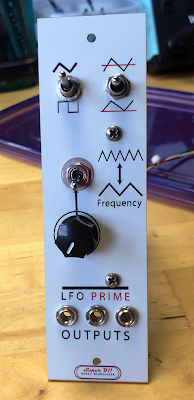
| The AudioDiWhy analog LFO, circa 2003, with a new front panel.....with SuperD! Livery--thanks Iggy for analog assist! |
OK, first up: I needed a development platform. The main MCU used for the project was an 8 bit Atmel 328P; it's reasonably simple to program, well documented, inexpensive, can be found ready to use on a USD$10 Arduino Uno R3 clone (which means not having to wire up a crystal and so on).
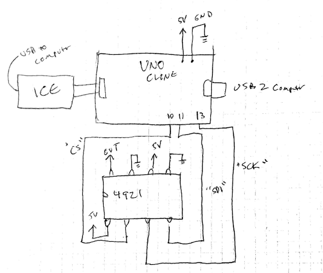
The 328P has 10 bit ADC's already built in; good! I still needed an external DAC, and SPI is easy to use, so I used a Microchip MCP4921. It's 12 bits--that means the waveforms the DLFO creates will have 2^12 or a maximum of 4096 voltage divisions. That resolution I figure will be good enough.
 |
| A-DiWHY: "Hey Mom! Check out the 4921 it's PDIP! It's SPI!" Mom: "get a damn job!" |
The rest of the development platform I used is the same one I've used for the past few posts: a Windows 10 NUC PC; Atmel Studio 7, and an Atmel Ice programmer.
 |
| UNO to 4921 DAC wiring. For CV analog in, controlling the frequency at output, I used PortC pin 1 |
But! the 328P doesn't natively support I2S, 44.1K sample rates, or anything like that. How am I going to make a voltage to low frequency converter out of it?
Turns out, there are lots of ways.....
First, I needed a steady clock upon which to base the rest of the design. There are 3 timers in the 328P-- 2x 8-bit timers and one 16-bit timer. I was a bit intimidated by AVR timers at first, but after some reading it turns out it's actually not that complex. The timer can be set up with just a few lines of code--we want to use "CTC mode" for this project--a great web page about AVR timers is here.
The code fragment I ended up using:
//********TIMER************
// Set the Timer 0 Mode to CTC
TCCR0A |= (1 << WGM01);
// Set the value that you want to count to
OCR0A = 0xFF;
TIMSK0 |= (1 << OCIE0A); //Interrupt fires when counter matches OCR0A value above.
sei(); //enable interrupts
// in atmel s7 sei() is flagged as red squiggle due to
//"intellisence" beautifying,but will still compile. Doh!
//TCCR0B |= (1 << CS02); DO NOT USE, this turns off clock
TCCR0B |= (1 << CS01);
TCCR0B &= ~(1 << CS00);
//********TIMER************
OK what next: we need the timer to signal the LFO to do something. For that, I needed to use Interrupts. Wait: Interrupts? They always intimidated me while using Arduino sketch--they never made much sense and I followed code examples until they sort of worked--but here, I had to know what I was doing.
Good news: turns about again, after some reading: not that complex. A good video about how 328P timers can be used to create interrupts is here; a good web page is here.
Each time the 8 bit timer (I used timer 0, but any of the 3 would have worked) I had the code throw a hardware interrupt. That creates the steady heartbeat for the rest of the design.
Now we have a counter that counts upwards until timer0 matches the value in register OCR0A, then, it throws an interrupt and starts the process over.
Next I declared a volatile unsigned variable 16 bits wide called "c". Remember in C you have to think carefully about variable casting! The interrupt routine is a simple increment statement for this global variable:
ISR (TIMER0_COMPA_vect) // timer0 overflow interrupt
{
c++;
}
(There is something strangely poetic about literally using c++ in a program written entirely in C right? Wait, I need more fumes....)
OK we now have a timer that creates an interrupt on a regular basis, incrementing a global variable--what's next?
Lots of ways to go here, the most common is to a create a values that represent the waveform, then walk the array and send each value to a DAC. But I decided to go a different route: a cheap and dirty (sounding) way to control frequency from CV is to allow a certain number of interrupts to pass before incrementing or decrementing a value to be sent to the DAC. If I wanted the waveform to increment from say 2000 to 2001, I write the 12 bit value for 2001 to the 4921 after waiting for a certain amount of interrupts to occur. More interrupts means a lower frequencly waveform at output, less interrupts means a higher frequency.
That means: for a square wave, I can send 0xFFF for on and 0x000 for off after some number of interrupts pass. For a ramp, increment by one, and then when 4096 is reached, start over at zero. For a triangle, count up then down again.
If you're still trying to figure out my approach, let's look more closely at an example--let's create a ramp wave.
For the first 12 interrupts of a ramp wave looks like this:
 |
| By incrementing the global variable c by 1, 4096 times, we can get a pretty decent ramp wave. |
Again, lots of ways to fix this--I could have used an external op amp inverter for CV instance, but trying to do this all in software I subtracted 1024 from the value read at the ADC input--easy!:
uint16_t rate = 0;
rate = 1024-freq;
That was really simple, and worked.....now CV fully CCW is slowest and CV "fully CW" is fastest.
Next, let's get some output going.....after studying the 3921 datasheet I created a simple .h and .c file to control the DAC to do the heavy lifting at output. Find that in the github zip, here. With all this, all sorts of waveforms can be generated, and I can reuse the 4921.c and .h files in other projects--cool!.
The final part of this is to control the maximum frequency the 5V CV generates. This took some trial and error and going over and over the math, but eventually I found an unexpected trick: I can add to the value sent to the DAC to increment the maximum speed at the expense of the waveform's resolution. There are limits here of course--I can run the triangle wave so fast that it starts to distort because too much data is dropped--but overall this software kludge (?) worked, and for the square wave, the value of this "add" has the added benefit of determining the maximum frequency to about 5%.
count = count + WFMFREQ;
uint8_t CMSB = count >> 8;
uint8_t CLSB = count & 0xFF;
write4921(CMSB,CLSB);
OK, so what's next? I need to create clamped hardware buffers for CV to not fry anything inside or outside this circuit. I will also probably tie the "rate" value WFMFREQ to a pot or switch. Update--no, I solved this a different way, post for final software build is coming soon.
In the meantime, the DLFO in its current baby-step form produces decent waveforms--I have created functions for Tri, square, and ramp, and creating more--saw, random, expo, etc., should be pretty easy.
the problem--or strength--of this design is that for some waveforms at some freqencies you end up with very few sample points. So I expect the output of this LFO to be "gritty", but for now, that's OK. Maybe just stop here--do I really need more LFO's? Not sure. These last 10 days or so was an exceptionally good learning experience and now perhaps I am no longer a full "C newbie". Getting another stupid LFO to work in my rack almost doesn't matter at this point. Update 4-8-21: right, but I had to see this through. PCBs designed and off for fab. Assuming I have a morning or two, I will build it to see how this design can be further refined. UPDATE! embedded C DIRT-LFO works! Post is here.
OK enough C for one day. If you want to stretch out your brain a bit, maybe you want to put Sketch aside and try something like this. Leave the fumes aside for a week? For me anyway, it was a lot of fun. AHOLA!


