This one started when my 50-year old (!) Minimoog bit the big one.

Its Loudness Contour Envelope Generator croaked; it would work on occasion if I tapped on the DECAY TIME knob--so, a faulty potentiometer?
I took it to an expensive vintage electronics repair shop 45+ minutes away.
Sadly, $600USD later, after "fixing" it, the sustain knobs sent CV to the VCA and VCF, even if a key wasn't depressed. Need to do a soundcheck? Have the roadie crank up "Sustain Level". Done.
Not a feature, a bug?
 |
| MiniMoog "Modifiers" section. On my vintage Mini this is transistor/resistor/cap/diode only ADSD Envelope Generator. |
Looking at MiniMoog schematics (here and here), its EG's are discrete; no IC's.
I had (and still have) almost no experience with circuit design from this era: pre-integrated circuit, but post-vacuum tubes.
The more I tried to study the schematics and follow signal paths the more my brain hurt.
I tried to simulate the MiniMoog's Loudness EG using Falstad:
 |
| Get a functional (pun intended) MiniMoog Loudness Contour simulation here. I couldn't get this Falstad simulation to work, but Mod Wiggler's "guest"--the same superhero who helped save the triangle to ramp design in the DVCO project, here--fixed my broken Moog EG sim. Yeh! |
Cool...I had a working simulation, but try as I might, I could not duplicate the odd "Sustain to CV" fault on my beloved MiniMoog.
So--I did what any rational person would do--I gave up.
Of course, I couldn't leave it alone.
Instead, I went down a design using only discrete rabbit hole.
Nevertheless, I dug further into Falstad to (try to) whip up discrete simulations for LFO's, preamps, and EG's.
I quickly learned that, like my brain, the UI for Falstad wasn't up to some of it.
Which led me to--sorry about the long intro, folks--the NGSPICE simulation abilities built into our beloved EDA software--KICAD 8. Simulating discrete component circuits for me was way easier than endless breadboarding.
TUTORIALS
GETTING STARTED--FAKE DC POWER
 |
| Spice VDC component |
 | ||
| Once +5VDC was defined somewhere in my schematic, I found I couldn't define a Spice VDC for +5V again or cryptic errors would appear when it came time to simulate the circuit. |
 |
| Simulated +/- 15V Power supply |
555 ASTABLE: FIRST SIMULATION
Back when dinosaurs roamed the earth I built an astable using the venerable 555 IC. As an homage, for my first simulation using Kicad, I started there.
 |
| 555-the newbie's IC! |
But! Putting a 555 symbol, passive components, and my +5VDC power supply into a Kicad schematic, then starting the simulation (steps to start a simulation follow shortly), threw cryptic errors.
Turned out: the simulation didn't know what to do with a 555 IC, since its behavior needed to be defined or "modeled".
I found models for just about every common component I could think of using Google searches--often they are found on manufactures' websites. I gathered a few model files I thought I'd use frequently and put them on Github--here.
Here's a quick summary of how to add a model to a Kicad symbol:
- Select the 555 symbol in the schematic
- Tap "e" key to select properties
- Click on the "Simulation Model" button:
- Point the component to the 555 simulation file and choose the 555 model:
 |
| If the path to the file might change on other computers you work on, consider using a Kicad variable like ${sim_model} instead of hard coding D:\[path to this] [path to that] |
Click on the PIN assignments tab to make sure the pins from the model map to the pins in the Kicad symbol:


I chose: "OP - DC Operating Point". OP was akin to using a voltmeter, so I figured--easy?

....and to my surprise it showed voltages and current for a sim as a snapshot in time: IT WORKED!!!
Cool!!!!!
SCOPE A DOPE
Seeing voltages and currents at a point in time was great, but I wanted to take it up a notch: see an X as time and Y as amplitude.
I put the 555 astable schematic into a hierarchical sheet (a brief how-to covering Kicad hierarchical sheets is here--go to the bottom of the post).
Using this 555 astable to generate a couple of pulses in 30 seconds I crafted a three transistor attack/release envelope generator:

 |
| TRAN--something the GOP will outlaw before long? No, blogs like this go first. |
| I found that making time steps too big or too small could bring the simulation to its knees. For this simple A/R function generator, plotting every 10ms and doing so for 30 seconds did the trick. |
With the simulation successfully launched: to choose the voltage I wanted to see plotted over time, on the right column I chose "V(OUT)", indicating the label I added to the AR schematic seen above.
I ran it and it worked! The V(OUT) looked pretty good--attack and release resistance impacted the circuit's peak output voltage but for 3 transistors: good enough.
 |
| I also needed to get a 2N7000 simulation model for this as well. I found it here--again, a manufacturer's website is a good place to start your model file journey. |
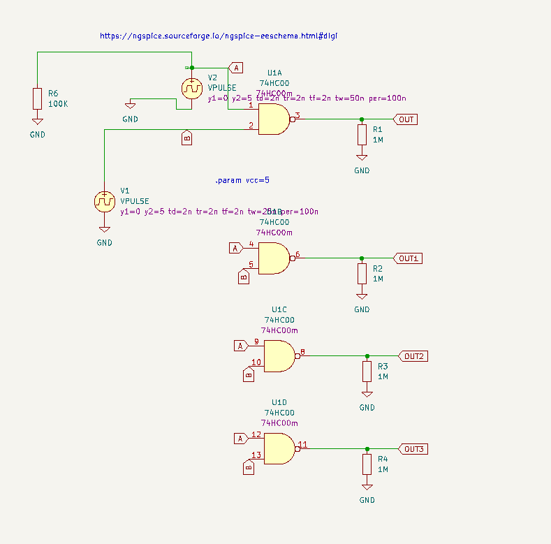
DIGITAL SIMULATION
- I tied outputs I wanted to see in my simulation to an 1M resistor, which is in turn tied to GND. Otherwise, the simulation wouldn't work.

- I made sure I added this text to the simulation's .kicad_sch design (this assumed "5V = high" logic):
 |
| I have no idea why this is needed....just do it. |
- I didn't need to worry about the power pins on a simulated digital IC, at least for the 74xx series mentioned in the video.
- Since I was doing a transient analysis of a digital simulation, I unchecked "Save all Currents" and "Save all power dissipations" and selected "PSpice and LTSpice" as my "compatibility mode" (you knew this, right?). Otherwise the simulations throws cryptic error and warning messages and may not run.

 |
| Notice that no power section "E" is needed. |
 |
| Output. |
OTA's
I simulated those too....took me a day to figure out I needed to use the VSIN (voltage) spice part, not the ISIN (current) part. Doh! That simple mistake tripped me up for hours.
Again, you can get the model files I have tested working with Kicad/NGSPICE here.

13700...Could only find a model for 1/2 the IC. The "1/2 LM13700" symbol is available as in the library file found here.

 |
| CA3080 |
 |
| Seems worked: green is input sine, output is amplified signal (I got the 13700's built-in Darlington buffer to work, and also an op amp based buffer) |
PLOTTING FREQUENCY RESPONSE


Good for trying what-if's, dropping in different cap and resistor values--seeing what happens--why do math, ever?
THIS BLOG'S SPONSOR!


No comments:
Post a Comment