I had an idea for a new circuit, inspired by the "source of uncertainty" thinking from the old Buchla designs of the 70's. Design goals: a random 0V - 5V signal I can use for gates (for instance, triggering the sound of water dripping--that at times should be pretty random). That's pretty easy. For extra credit, also have a random CV out that matches the random gate.
I started to think about how best to put that together.
I can do that with analog circuitry and if I chose that route, many of the blocks below I already fabbed and tested working, in the form of small PCB's. For instance, a noise generator. I have a working Sample and hold PCB as well, but haven't posted it yet....I will soon.....
I think the analog circuit would have to look like this:

I started to look into easier ways to do this and in about 2 seconds discovered the world of Arduinos. You probably live on Mars if you mess with electronics and don't know about these little dudes--I figure it's a home robot maker's dream, right?
But once I dug into it, there are a million and one Arduino uses for all sorts of DIY audio. It's great for sequencers, cheap DCO's and the like, but to me, it has it a lot to offer for CV projects as well.
I can't say how much I love these things.....low cost, well documented, has some free online simulators and has tons of add ons like DACs and ref boards whatnot, making it perfect for a circuit like this. All affordable....
The disadvantage of Arduino for audio: it seems too slow to be useful for more complex apps like granular sampling, it has no built in DAC, rather PWMs that can be pressed into DAC like service with a simple filter on it's output. It only has 2 external interrupts. Blah blah?
But overall, not bad at all, especially for the price to get things going.
OK, let's get into that? I bought a Uno and nano online, downloaded the IDE to an old Mac I had lying around, and found out pretty fast: with Arduino I can redesign all the blocks above to something much simpler:

I won't get into "getting started with Arduino"--it's everywhere on the web; if you're new to this you might want to run through a few really basic tutorials from the Arduino site....If you've every programmed in something like Perl or Python or PHP, one of those "be sloppy and it'll still work" high level scripting languages, you can do a lot of the Arduino basic coding in your sleep. it's really, really easy!
As far as sims, I found I could do circuit simulation (at least for simple things like this) on a site called Tinkercad. Log in is the same as Eagle since both are owned by Autodesk. Cool!
Over a 3 day weekend, working a few minutes here and there, I fabbed up some ideas for the random CV/gate and came up with this, which seemed to work:

I can't yet figure out how to pubicly share this Tinkercad thingy, but whatever. The good news, when I power the sim up this works--the LED blinks randomly; the pots control speed, and the OLED sim shows varying voltages. I'll post the Arduino sketch on my website when this project is done. Update: works--sketch is on GitHub.
The problem (?) I found with Tinkercad is that when the circuit begins to get a tiny bit complex--the PWM to control output to DVM for instance--things slow WWWAYYY down. Tinkercad still seems useful for simple simulations and basic coding practice.
OK with that and my Arduino NANO in hand along with an Adafruit MCP4725 DAC I put a few components--very few--on a breadboard to see if I could get this to work.
To my amazement within about an half hour I had everything working. I just copied the tinkercad sketch to the IDE and wired up a handful of parts. Is this too easy?
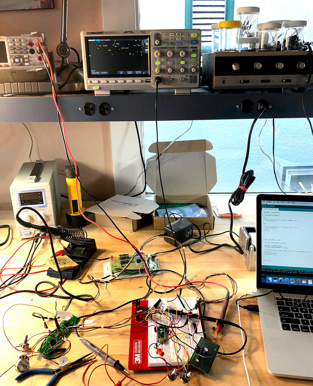 |
| Random Gate--on bench! |
 |
| The thing on the right is a 10V supply--more details below. The pots control the speed of the random gate |
 |
| DC output of the Random Gate--grid set to 1V |

well that was fun! Still to do:
- The adafruit DAC for this works great, especially vs. some sort of PWM but output, but can't find an Eagle library for the part. I will make getting that going a new post since I have very little experience with creating new parts for Eagle. Ah another learning experience!
- Still need to tweak the overall design, adding the buffers at output, design a front panel, and so on.
- I need to see how it sounds. There is a big difference between hearing electronic music and seeing little trace patterns dance around on a scope. Stay tuned!!!


No comments:
Post a Comment