I use Autodesk's Eagle for PCB layout.
So this blog entry will only be useful to you if you use Eagle vs. other means of laying out PCB's.
It will also only be useful if you use Windows; I suspect the Linux and Mac versions of Eagle are set up differently in terms of where the files go.
And-- I am using Version 9.0.1 of Eagle as I write this; Autodesk changes Eagkle all the time, so I can't guarantee this will help you if you're reading it 3 years from the date of this post.
If you don't know Eagle pretty well you want to skip this blog entry, it won't mean squat to you. But if you use Eagle all the time, as I do, it might be useful. OK without a lot more blah blah:
Here is the issue.
When I am designing a board layout, a series of Pads might look like this:
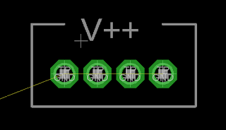
When how I want it to look is this (note the absence of what Eagle calls "NAMES")
Pads without names is useful in some situations--I can now use text tool on the tNames layer to silkscreen a clear callout, in this case V++:
So how can you remove names? You can't call a named part "" (so, no value) or you get an error when saving.
The only way I could figure out how to do this is change the actual part itself, getting rid of the >Name placeholder for each part I want to use on my board, and save it in a custom Eagle Library.
Fortunately it's not that hard to do.
Here are the steps:
- Close Eagle if it's open.
Create your own library after making a copy:
- The libraries that come with Eagle appear to be read only.
- You will have to copy an existing Eagle library to a new custom location you create.
- In my case I added a new folder to Dropbox so I can use my custom libraries across different computers, but any folder you have to which you have modify privileges will do.
Tell Eagle where you are going to put your custom libraries.
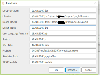
Go to Options > directory, click in the Libraries field to add the new folder you created for custom libraries.
Click Browse > Open.
Navigate to your custom library location and click OK.
Eagle will now look not just to its default locations for libraries but to your new folder as well.
Copy a library into your new library repository so you can edit it.
Hint: Eagle provided libraries in Windows 10 and probably Windows 7 live here:
C:\Users\[your username]\AppData\Roaming\Eagle\lbr
You knew that right? You may have to unhide hidden system files to find this content.
- Use Windows search and look for a library like this one:
testpad*.lbr
- Once you find it, copy the testpad*.lbr file to the new "personal" library folder you created above. Yep, all you do to "import" a stock library is copy the file to a different location.
Edit the personal library.
- Close any boards, schematics, etc., you have; you must be back at the Eagle "Control Panel" (not to be confused with Windows control panel!)
Now issue the command:
file > library > open
Open the personal library you just copied to your new folder.
Again, try as you might, as far as I can tell, users cannot edit libraries that were installed when you got Eagle going--only ones you copied somewhere else. Am I wrong about this? Anyone?
Time to edit--I am now going to edit the testpad.lbr library, and specifically the group of parts called "TP":
Expand the lbr file as you see on the left of the screenshot above, then Right click where I have the Blue Hi-light, the TP set of devices....I do this because TP has the specific pad I want to modify
Once selected, right click, and from the pull down, left click Open In Library".
A new window opens--the library editor.
- You will see a column on the right....select the individual part you want to edit by left clicking on it.
- Then right click on the part that needs its name blitzed--in the screen shot below I have circled it in red:
This takes you to the package editor, where you can get rid of the part's name--choose the garbage can icon, then left click on the + to delete the part's name:
You can also change the description by clicking on the description link and adding HTML for the part's description. Maybe change description to "TEST PAD-no name"
After the name is gone, hit the save (floppy disc) icon.
To change more parts, go to Library > manage devices and start the process again by choosing the next part you need to alter.
Using the Library
You get a library of many pads with the Names already removed from my GitHub. These are libraries where the entire TP device collection--about 20 parts--all have their names removed....I use this any time I want to use Text on the tNames layer vs. part names.
To use these parts, fire up your schematic, and use add > library manager > browse and find and then select your custom library. Pick the custom parts you want to use and drop them into your schematic.
For ones with the names blitzed in the manner above, the schemo will still show you a part name, but on the board it will be sans name.
UPDATE: I have used the "nonames" parts above several times now for different PCBs. So far, all seems to work. In the meantime, if you have comments, questions, or find a mistake in this blog entry, please comment below so I can fix this thing.


No comments:
Post a Comment