This is the third entry about building a so called "Synth DVM". If you are interested in the last 2 posts about this, here are links to part two and part one.
OK I have a working prototype on my bench, and I am having 5 boards made up for the op amps and Nano, from EasyEDA, they should be here next week. Assuming that works I'll get a front panel made....
In the meantime I'm trying to finish up the TFT display programming for the project. I am using the Adafruit GFX library, discussed in part two...
For the most part once I found decent code examples the TFT coding has been pretty easy, so I made it harder on myself--I decided that in addition to a simple voltage readout I want an analog looking "VU style meter" for the DVM, that shows a needle that points to -10V, 0V, 10V and all in between.
I can see reusing this for all sorts of audioDIY since the whole voltmeter thing with Arduino seems super easy--RMS conversion for displaying AC audio levels? Arduino driven compressors with a VU to display level reduction? A needle to show current values when paired with an INA219 current sensor? A thousand and one uses....
That's the problem with software--you're never done!
The code basics for getting an old school looking meter going isn't that hard, the first thing I had to work on was having the meter needle turn itself off before it changed to a new position with a minimum of flickering but I think I solved that.
You can get the prototype code off of my GitHub repos, but the salient code to get this working is this:
void loop()
{
//[…. code for numeric readout....not part of VU]
//get vu meter going
meterx = (sensorValue * .1) + 13;
if (meterx != lastState)
{
tft.drawLine(lastState,64,64,125,0x000);
tft.drawLine(meterx,64,64,125,0xFFF);
}
lastState = meterx;
delay(1);
}
meterx is a float that senses what is being read from an analogPin. I am saving the value during each loop, and then comparing it the next iteration. If meterx changes--blank and redraw, otherwise, leave it alone.
It works--the VU moves in concert with the read voltage, and it appears to be accurate and linear and the flicker isn't too bad (extra credit: lastState is long, not float, which improved flicker--strange, I thought that wouldn't work at all?)
The "13" pixel x offset centers the meter correctly on the x axis (128 Pixels, pixel 64 is center, we read 1023 gradiations divided by 10--do the math....) of the TFT.
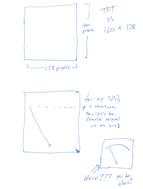
Here is the problem:The needle for the meter is not a constant length as it sweeps across the TFT and it should be.
Since Y is a constant in my code above, the needle "gets longer" as it approaches the far left or right side of its trajectory. That doesn't look analog--at all!
I sat up at 3AM trying to figure out a way around this--at each refresh, put a bitmap of a semi circle over the needle, but wouldn't that flicker (and take up a ton of memory)?
some sort of sine/cosine kungfu?
A lookup table that reduces Y value depending on "meterx" value?
All of these feel like a kludge to me.
I can't figure out an elegant way to do this--there is a "drawFastVLine" function in the GFX library, but it can only draw vertical lines of a consistent length, not one that moves on a central axis.
I have no idea about the best way to solve this. I might post it to some forums and it's time for more research. I guess it'd be best if I could expand the C++ library for Adafruit GFX to add a method "CreateMovingLine()" or "createVisibleRadius()" or something.
How deep do I want to get into this?
Here is a quick diagram of what I am up against. Any ideas anyone?
(UPDATE electro music forum user says "use an array". Doh. Did this and it worked. I was not thinking about this issue simply!
I'll post the results one of these days.)
Subscribe to:
Post Comments (Atom)
-
Hello again . I am fully recovered from Covid. It's time to keep marching forward. After finishing several projects based on Atmel...
-
If shelter in place has made you a listless here's a suggestion: entertainment is an AliExpress click away. This time let's check ou...
-
I had so much fun last time getting a TFT working with AVR embedded C that I thought why stop there, let's get an OLED display going a...


No comments:
Post a Comment