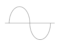
To review, what does this mean?
It means you start with an AC signal like this:
 |
| Figure 1: standard Sine Wave |
And you offset it a few volts above ground so it looks like this:
 |
| Figure 2: sine wave with DC bias offset |
The B.O.W.A.L. circuit from last time let you tweak the bias with a potentiometer.
But! Wouldn't it be nice to be able to do the same with a control voltage?
Turns out it's not hard. We start with the same PCB:
Then add some wiring instructions which you can find here. And yes I realize that the PDF is hard to follow (crappy handwriting). Hopefully this next diagram helps--it summarizes the 4 main wiring mods you need to add to hook the op amp stages together to make this work.
Wire all that up and you have 2 fully independent, buffered bias offset circuits; feed in CV and out comes the input sound or another CV, offset by the amount of CV at the "bias" input. Easy!
Some bench photos. Means not much to anyone but me, but it makes me remember the zen times at the bench putting this module together. That's the good thing about being a blogger--as long as you're not overly offensive, you can post any damn thing you want.
Like Big B.O.W.A.L., Small B.O.W.A.L. worked the first time without kludges, tweaks, and changes. Two in a row. I am trying to stay humble.
 |
| The wires here turn four channel BOWAL into two channel Small Bowal |
 |
| Skiff? We don't need no stinking skiff! |
 |
| B.O.W.A.L. brothers.... |
 |
| Bench B.O.W.A.L. |
Still with me?
Interesting synthesizer patches may be imminent when using CV to offset an audio or control voltage....a lot of times you want to get rid of DC offsets, but not always. Hear what Small B.O.W.A.L. sounds like here. As usual, no effects, tweaks, tricks etc. for this demo. This is all bias offsets using the circuit in this post.
details about the demo:
00:02 CLASSIC MOD F/X
- Slow LFO goes to Small bowal input.
- Small bowal CV input source (for bias offset) is from an AR
- AR is set to immediate attack and moderate release.
- Post-gate LFO climbs down from an offset of about 3V above ground to zero volts.
- Sent this offset LFO CV signal to a mod input of a VCO. VCO set to ramp wave
- So you hear the warbly mod pitch descending as the CV offset goes from around 3V to 0V.
- This is a popular mod trick for modular synthesis. A bit tired perhaps.
00:20 Distortion unit becomes waveshaper
- Sine wave to small bowel audio input.
- DC offset of this sine wave with slow LFO, maybe 1V P/P
- Feed this signal into input (1) of the SON OF ZENER
- The other channel (2) of son of Zener is a triangle wave.
- You end up with something that sounds a lot like a Serge Waveshaper meets VCA. I have no idea why.
00:55: Goose a Korg MS20 style ring modulator
- 1K Ramp wave > Small Bowal input.
- Small bowal CV input is modulated by ADSR.
- So ramp wave is starting with a DC offset and falling back to 0V
- That's fed into X input of the ring-mod.
- Y input of Korg Rmod is ramp wave, unadulterated
- You end up with the ringmod effect that is not audible, then suddenly very audible.
1:21: Odd things happen when you DC offset audio into a balanced modulator.
- Not everything will sound good here, you have to mess around.
- pulse wave (audio) offset by SB.
- SB bias offset modulated by slow LFO.
- SB audio output to Y of 3080 or equivalent balanced mod.
- X in to B-M is another pulse wave.
- Balanced mod out to VCF > VCA
- You can get all sorts of very odd sounds from this. If you have a balanced modulator, without AC coupled inputs, try messing with putting DC audio offsets to feed X & Y inputs.
OK next up I have some guest circuits from reverselandfill.org. Stay tuned!


No comments:
Post a Comment