
After a few days at the bench, the answer is a qualified "probably not".
What you can do:
- You can use PWM to get different resistance values out an opto coupler aka "Vactrol" aka "vac". See the last post about this here. From that post: if you want to control a VAC with an MPU, PWM is a good way to do this.
- You can sweep through PWM values, at least lower resistance values, and record the steps into an array. The Vac will mostly behave.
- You can then do math and look ups on the array to change the VAC's behavior.
OK, After a grueling (?) + frustrating (!) 4 or so days messing with this, I mean for hours each day, my conclusion: there is way too much variation in the high-resistance range for the vacs I tested for them to ever behave in an useful, linear manner. This makes Vacs poor candidates for linear applications requiring resistance values above about 100K-200K.
Sorry.
If you want to mess with this--feel free to prove me wrong, please! read on:
 |
| Uno PWM-VAC madness..... |
OK, first thing to do is to make your Arduino into an Ohmmeter, preferably with a good degree of accuracy. There are a lot of posts on the web about how to do this, an easy to follow vid is here, while the most in depth pdf I could find on the subject is here.
But let's make it harder OK? I tried for two frustrating days--and I mean all day, for two damn days, to get this ohmmeter idea working on an Expressif ESP32. ESP32's can easily be set up for 15 bit PWM with a lot of easily adjustable parameters, and 12 bit A to D conversion. This makes it a perfect candidate for this project (it's also much faster than any Arduino I've tried to date).

But I couldn't get the ohmmeter part of the project working on an ESP32 with any degree of reliability. Eventually I gave up. CRAP. I couldn't get anything better than about 80% accuracy for ohm readings, best case, and most often way, way worse. Even for 1K. Even for 10K, even for 100K. Forget about reading vacs--that's trying to read normal resistors, using my tough-n-ready Fluke 117 to A-B what the ESP32 was coming up with. Nope, don't like it. Not one bit.
With an Arduino Uno, I could easily get 1-2% accuracy to about 100K or better just slapping in parts.
 |
| Greatest thing since sliced bread--so how come simple Ohmmeter sketches didn't work? |
So I used an UNO with PWM set to 256 steps and the 10 bit A-D pot.
Basic hookup is this:
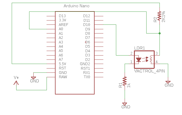 |
| I used an UNO on the bench, not a Nano, and V is 5V not 5.5V. Whatever..... |
Here is the code:
//initialize pins
const int voltRead = A0; // Analog input pin that senses Vout--used for ohm conversion
//initialize ohmmeter
int voltValue = 0;
float Vin = 5; // Input voltage
float Vout = 0;
float buff = 0;
float buff2 = 0;
float Rref = 2000; // Reference resistor's value in ohms
float R = 0;
float R1 = 0;
float R2 = 0;
float R3 = 0;
//pwm stuff
int x = 0;
const int pwmPin = 10;
void setup(){
pinMode(voltRead, INPUT);
pinMode(pwmPin,OUTPUT);
Serial.begin(9600); //breakfast serial
}
void loop()
{
for (x=0;x<256;x++)
{
analogWrite(pwmPin,x);
voltValue = analogRead(voltRead);
buff = (Vin * voltValue);
Vout = (buff)/1024.0;
R1 = (Rref * Vout)/(Vin - Vout);
voltValue = analogRead(voltRead);
Serial.print("analog read is : ");
Serial.println(voltValue);
buff = (Vin * voltValue);
Vout = (buff)/1024.0;
Serial.print("x is: ");
Serial.println(x);
Serial.print("Vout is: ");
Serial.println(Vout);
R2 = (Rref * Vout)/(Vin - Vout);
voltValue = analogRead(voltRead); // Read VAC voltage divider
Serial.print("analog read is : ");
Serial.println(voltValue);
buff = (Vin * voltValue);
Vout = (buff)/1024.0;
R3 = (Rref * Vout)/(Vin - Vout);
R=(R1 + R2 + R3)/3;
delay(1000);
Serial.print("Resistance read: ");
Serial.println(R);
}
}
//=================
(Yes I know the analog read thing can be made into a function vs repeating the code 3x. I'm too lazy. You do it.)
And yes, you get better readings if you change out the reference resistors to say 1M when you are reading high VAC resistance values. A good article about using a 4066 for this is here; uh-huh I tried a CMOS switch for autorange; even with 300K to 1M reference the values read from the vac above 150K-300K bounce around like a coked up hamster on steroids--not usable nor stable. Reading a 1M resistor in this setup--yes. Accurate. Arduino Ohmmeter works fine even with the ref resistor pretty far off!
With a Vac--nope.
 |
| How about using a DAC vs. PWM? Tried that too! using a 4725DAC. Easy to kludge in--info here. But--Same problem. Crappy response at high resistance readings. |
OK Depending on the vac, this means we have a usable response curve from about 200K (maybe, maybe less) to about 2K, but most of the useful action is between about 10K and 2K. Is that good for your project? Probably not.
Going forward: Next thing I'd do if I were to continue this work is to put the ohmmeter values into an array, something like a[x] = R for each value of x. I messed with this too but won't bore you with all the code. If you've made it this far, you can figure the array part out.
Then the array could be sorted, you could use the map function to further goose the analog readings, or math in general could be done to elements of the array as discussed in this post.
But!!! I can't immediately think what's next for ArduinoVacLandia.
In the course of messing with this I started to think the best use case is to maybe not try to do a lookup table or a bunch of feedback to an analog pin. Instead use the PWM capabilities in an ESP32, driven by buffered and voltage divided CV; that all works. Then further tweak the incoming CV with a map function, simple addition/subtraction/division of values, and who knows what else, to get the VAC to do interesting things.
But my original idea of linearizing a vac over a large range, I think, is probably not going to happen. For that, a digital pot has got to be a better choice.
So is this the end of the story? until I bite the big one: no. I will probably revisit controlling VACs with MPUs down the road, but for now it's time to move on. I'll bet if a lot more time is spent, figuring out why the ESP32 didn't work, using a 4051 to switch between 8 reference resistors, doing a lot of math, finding some opto out there in optoland that isn't squirrely, or whatever, yep, you can take this further.
Hopefully you have more fun than I did, because a lot of these last 3-4 days at the bench kinda sucked.


I just started my vactrol journey and had a kickstart thanks to your blogposts :-) I also get to a point where I can kind of reliably measure a logarithmic response between Arduino PWM value set and resistance response. Right now I am experimenting with a digital pot in series with the vactrol LED, to see if I can get finer grained control by changing voltage and resistance together and then linearize by picking smart PWM and digi pot resistance combinations. Probably will not work, but then I just had this funny idea a minute ago to actually use two vactrols in series to linearize the resistance response and let them work in opposites: if I set the PWM output for vactrol 1 to 200, set the PWM output for vactrol2 to 55 and so on withint the 0-255 boundary. I'll give that a shot tomorrow :-)
ReplyDeleteHi Thomas: Fantastic! Please let the blog know what you come up with, there must be many use cases for MCU's PWM-ing the LEDs in vactrols, the ideas you describe are things I have never seen in the wild.
ReplyDeleteThe digipot combined with vactrol idea did indeed yield linear results on the vactrol resistance between 200 and 1M ohms. I am experimenting with digitally controlling a guitar pedal audio circuit, so I did not want to use the digipot directly in the audio circuit to avoid the zipper noise when changing resistance values and because most digipots are constraint to control voltage within the power rails (which is usually 0...5V volts but a +/- 4.5V guitar signal.) Anyways. Just using the Arduino's PWM-out directly into a vactrol did not give enough current steps to manage anything linear, as you described in your post here. Then I added a 100k digipot as a variable resistor in series, so PWM -> digipot -> vactrol. And now for every of the 255 PWM steps I have 255 resistance variation steps on top to finer control the vactrol LEDs current supply. I used your voltmeter setup and ran two nested for loops from 0...255 for PWM and digipot resinstance, measured the vactrol resistence response and printed all that into a csv file. Then wrote a Python script that can take the 256x256 matrix of possible PWM/digipot combinations and their vactrol resistance and pick the right combination of input values to create a linear resistance output in 256 steps between (nearly) 0 ohms and whatever upper bound I want. The script then prints a lookup.hpp file to include into my Arduino project.
ReplyDeleteSeems counterintuitive at first to use a digipot to control a vactrol, but if you truly want to decouple an audio signal path from the digital control path, that seems like a fair idea. I'll work on putting all this together into a github repo with a README "blog" post on how it all fits together. Might be useful for others. Cheers!
I am interested in seeing this once posted. Thank you!
DeleteHi, what you have developed would be very useful for me, I am really interested on it. Would you mind sharing more details about the circuitry and the code you used? Thank you so much
Delete