
Yes, but there is a reason you don't see optos in every VC synth circuit. Vacs are the girlfriend who plays great bass but consistently smells bad: promising, but in many ways, far from ideal.
Let's break this component down, Sergio style:
The good:

- Vacs can take a relatively large amount of power at input and not blow up. Try that with your rare OTA or expensive digital pot (better yet, don't).
- Vacs can go into the M-ohm range where digital pots in my experience top out at about 100K.
- Vacs are, at face value, super super simple. In goes current, out comes resistance. Add a resistor to protect the Vactrol's internal LED and you have instant voltage control. Viola!
- Which means, you can drop it right into most circuits that need voltage control of resistance, as long as you can make due with "the bad" which Lee will present next.
The bad:

- Vacs are extremely non-linear, especially in the high MegaOhm range where their non linear nature gets downright silly.
- Vacs' non-linearities vary from unit to unit. For vac #1, 40mA in produces10K, another from the same run/same batch resists at 15K. Mr. Yuck.
- That means if you need 2 VACs in a given design, you probably have to match them for best results. Think 6V6s in guitar amps or NPNs in a Moog ladder.
- That also means if you need good linearity over a wide range, or really any sort of good linearity at all, you probably need to look elsewhere.
- Vacs are really slow. Unlike OTAs and digital pots, you can change your voltage and it takes maybe a couple of milliseconds (or more) for the Vac to "catch up"....bad, for things like VCOs etc.
- Vacs aren't made by the zillions, and some manufacturers have stopped making them altogether. So sometimes you have to look around to find the exact Vac you want and most often you have to make do with a part that isn't quite right.
The ugly:

- Unless you find optos surplus or make your own, vacs can be expensive--$5USD a pop or more.
- Physically vacs are big parts--there are no SMD versions of this I've ever seen.
- Overall the unpredictable nature of Vacs can, in some situations, drive you, the circuit designer, completely nuts. It's not always worth it.
Want more? A really good description of a vac, from Doepfer, is here. A previous AudioDIY post about them is here, my own Vactrol based multimode, low parts count VCF is here.
OK, Wrapping up this long intro: aaaah, the opto. Buchla's legendary low pass gate uses them, MakeNoise uses them, DIY compressors use them. I use them. If you don't use them yet, go buy a bag if you ever see them surplus, get them on your bench and do the messaround. Yes they will drive you crazy, but also, like the aforementioned punk rock bassist, hold your nose and have hours of fun.
OK without further Vacdoodoo: Here's part I of next batch of Vac-uuous--Vactaitious--Vac-trolius--AudioDIWHY posts: can we use an Arduino to tame a Vac?
Goes like this: I was lying in bed thinking about Vactrols (yes, I do do that) and figured the snot-slowness cannot be helped. But how to solve the other two issues--that one vactrol is never quite like the next, and Vacs extremely non linear. And then it hit me, bolt upright in bed: can we use an MPU to ameliorate!!!!

My thinking, in its simplest form:
- Use a resistor in series with the Vac LED and the Arduino PWM. The LED is a current controlled part....I am going to thus treat a Vactrol going forward as a non linear voltage controlled resistor and assume we always have that current limited resistor in series.
- Create a lookup table in the MCU (Arduino right? We all know how to program those)
- For CV input x, find the value for X in the lookup table, and send voltage y, which will produce the desired resistance for X, to the Vactrol.
- The idea is that the MCU > Vac circuit fragment can produce a "corrected" resistance for the Vac, ultimately giving you something approaching linear, making it much more musically useful.
- And if you can use a lookup table for linear, you could modify it for log or antilog as well.
Next I started to think about how to get the voltage out of the MCU. We could use an D to A IC, but to reduce parts count, let's try leveraging the PWM that Arduinos can produce.
Could it be that easy?
And a more out-there idea: we could make a second Arduino be a"table creator programmer" and then blast the lookup table created by MPU #1 into a second Arduino's lookup table. That might speed up deployment of this linearization MPU. This idea is still a bit (pun intended) "sketchy" but is still worth more digging around.
Who Needs to Work when there's AUDioWHY?
This idea went OCD on me and I almost didn't go to sleep that night but had to eventually (damn day job).
Before I got on the train, I posted on the E-M forum to see who has messed with Arduinos controlling vacs--post here--seems like that's a big no one--so let's get to work!
I did do some breadboarding the next evening to see if this was feasible.
Yeh, the basics work:

Next, put your ohmmeter across TP1 and 2 and yes, as the PWM duty cycle changes you will see some resistor action. I got something like 10K to 40K out of one of my junk box vacs in this extremely simple configuration.
Might be useful for something right off the bat, even without tackling the lookup table?

Mildred, can I get more? It'd be nice to get a wider resistance range out of this, and intuitively I figured the Ardino can't source enough current for that.
I put aside the Arduino for a minute (why mess with more programming at this stage?) and fired up my Siglent function generator.
Next I perfboarded a very simple current booster:
 |
| Pulse in is the pulse signal from a function generator. V+ can be 15V--change V+ to vary the resistance between TP1 and TP2 |
I tied the fragment above to the breadboard junk box opto:

I set the pulse frequency to 10K; used a 5V-0V pulse wave, varied the PWM as per the table below, and here's what I got:
at 4uS: 50K
8us: 30K
12us: 12K
100us: 4K
500us: 1.3K
999us: 870ohms
So we've created a somewhat decent 50K resistor here. We can't go down to 100ohms which would be nice--can't have everything but this is still useful.
I found that by experimenting with different optos, different C1 values, different pulse frequencies, and different duty cycles, I could get results in the 1K to 2M range, which might be good for something like a VC glide circuit. So in general, controlling a Vactrol from a PWM source works.
Or does it? A big problem I am grappling with as I write this post: at high resistance ranges things get unstable. The resistance from a single PWM setting jumps might around from say 1.5M to 3M. I figure I have to improve up the RC filter above to improve this, which I will work on in a bit. Stay tuned.
Bits and more bits: Grumble aka Big Dutch Ed from the E-M forum notes that the native analogWrite() Arduino method produces only 8 bit, 256 PWM resolution, and we might want something better. He's right. We could set up 16 bit PWM for the Uno, but it's kludgy, so let's see what else is out there.
I dug around and found the Espressif ESP32. Good news--many vendors make this processor into a sort of Arduino Pro Mini on steroids by dropping it on a board, adding a crystal, pins, vreg, etc., the usual Arduino type setup. For those, it seems that the PWM pins work at 15 bit out the box.
Wait, it gets getter: the ESP32 has 2 independent cores, Bluetooth and WiFi built in (so you could make your vactrol chooch from your cell phone?? Are you kidding me?), and its many development boards and clones of development boards can be programmed using the Arduino IDE.
And all for maybe $10USD a piece.
Holy IOT, Batman! ESP32 is a truly amazing bit of kit, especially at that price. If nothing else, this Arduino + Vactrol road has led me to what looks like an amazing inexpensive microprocessor I didn't know anything about before.
The Auto-table idea:
Final idea: how to speed up creation of the lookup table.
I don't want to have to hand-enter a lookup table each time I use a new vac. I was discussing this project with E-M member (and a neighbor of mine) MVCL and he suggested something more like this:

The idea:
Many more hours of fun ahead! Until next time, don't breathe the fumes.
UPDATE: Part II is here. SPOILER! couldn't get an MCU to fully solve the "crap linearity" issue. Still, this is a very useful concept, I think....
 |
| ESP32's. Arduino IDE ready MPU; Amazing power and features at a very, very low price. It reminds me that at our core(s), we human beings are good. |
The Auto-table idea:
Final idea: how to speed up creation of the lookup table.
I don't want to have to hand-enter a lookup table each time I use a new vac. I was discussing this project with E-M member (and a neighbor of mine) MVCL and he suggested something more like this:
The idea:
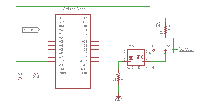
- Have D3 ouput, at start up, be a PWM duty cycle sweep
- Capture the output of "Sense" (a voltage divider) at analog input A0
- Use Ohm's law to compute the lookup table for linearization of LDR1 as the PWM is being swept.
- Blast that table into on board memory
- Turn off the table generation mode
- Use the other analog pins for CV
- Use the lookup table and go!
- You could run this routine to re-craft the table at start up which would accommodate things like changes due to environmental factors.
The issue here is that A0 is only 10 bit, but still, it's a better idea than using 2 Arduinos for this. This will require more work and thought, as always, but again, this all sounds doable, and is a much smarter approach than whatever I had rummaging around in my head.
Next up: I bought some ESP32's and need to see about getting the 15 bit PWM working. If those MPUs work as pulse generator with 15 bit PWM accuracy, I might get to building something that is musical soon. UPDATE: 12-18-19. ESP32 works great--I followed the vid here to get one going in Arduino-land, using a cheap Amazon ESP32 board, Fedora Linux, and the current version of Arduino IDE--and yes, Andreas Speiss rules.
Many more hours of fun ahead! Until next time, don't breathe the fumes.
UPDATE: Part II is here. SPOILER! couldn't get an MCU to fully solve the "crap linearity" issue. Still, this is a very useful concept, I think....


No comments:
Post a Comment