This is a continuation of the post started here--way back in April 2019--working on modding a Lunetta Noise! Oscillator circuit from the mind of Martijn Verhallen, found on his reverselandfill site.
It's a cool circuit on its own but sadly I can never leave anything alone.....
To mod this Lunetta Noise! circuit --I hope to have the module mods entirely done (finally!) in the next few weeks--I wanted a way to radically change CMOS Oscillator frequencies using CV, and figured a quad digital pot IC would be a way to get to that. Yes I could have used optos--been there, done that, e.g., here; why repeat something when you can do something completely different?
The pot I chose for the project--there are a lot of choices in digitalpotland--is the Analog Devices AD5254. Data sheet is here.
It's 8 bit, quad (4 independent pots on one IC) and uses the I2C communication protocol to change its wiper values among other things. Should be easy? Sure--there is a lot of information on the web about using digital pots with MPUs, such as here and here.
But I hadn't seen a lot about getting a quad digital pot ICs going with an Arduino--and AD datasheets can be pretty dense, so, let's try it....why not?
 |
| Dead ants! |
If you've messed at all with the Arduino wire.h library, you know that implementing Arduino I2C is easy as long as you read the datasheet for the chip under control carefully and understand exactly what sort of data you need to feed the I2C slave. A most-excellent vid from GreatScott!, where he has to decode an AD datasheet to get an I2C FM radio chip working is here; getting this quad pot going is the same idea.
(BTW as long as we are talking vids--a really good intro to I2C vid is here--highly recommended if you want to know how I2C works under the hood.)
Shut up already--Let's build! Nope, Not quite yet.
Here's rev 1 of the pot schemo and PCB:

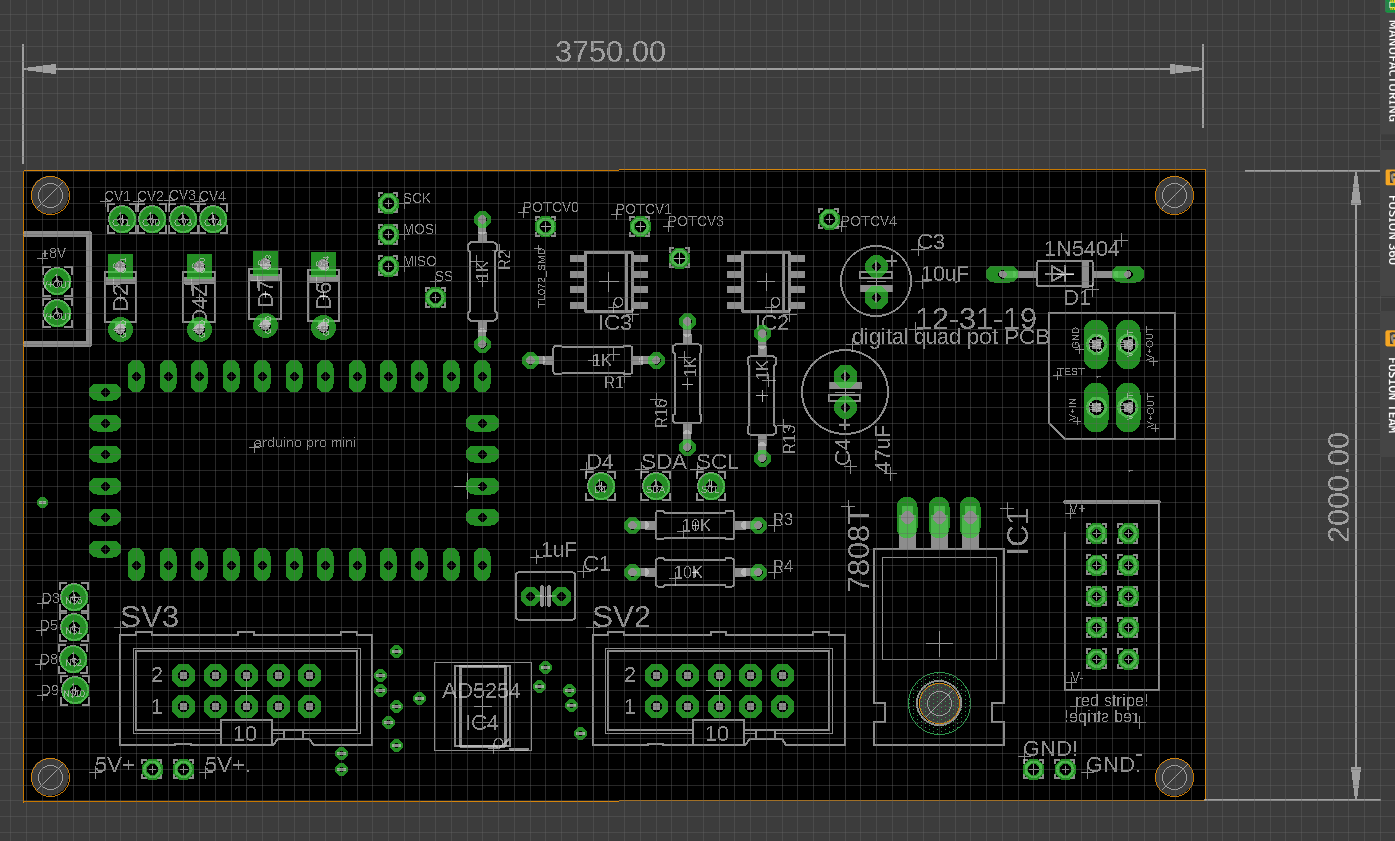 |
| The digital pot chip is the tiny thing bottom center..... |
The idea: in goes 4 CV's, which get buffered with 2x SMD TL072s, and regulated by 5.1V Zeners--this is old hat, I find myself using the op amp + zener fragment seen above over and over. So often that I built a dedicated board for it which you can see at the bottom of the post here.
The CVs are fed into 4 analog inputs in Arduino-land, which get A to D'd. Finally the Arduino translates what it sees at analog in into I2C data, and sends that to the the AD5254 IC to change its four wiper positions.
Piece of cake right?
Shut up already! damn!--just build it!!
OK the boards are back, I bought some AD 5254 chips from Digikey, and of course a lot of other parts were lifted from my parts junk box.....
With that in hand it's time to solder in the SMD chips first, and beware, the AD5254 is really REALLY tiny!
 |
 |
Holy smokes that's a small IC, but fortunately, I tooled up for SMD soldering already, and as I do more SMD work it's slowly getting easier. More info about how I geared up for SMD here.
 |
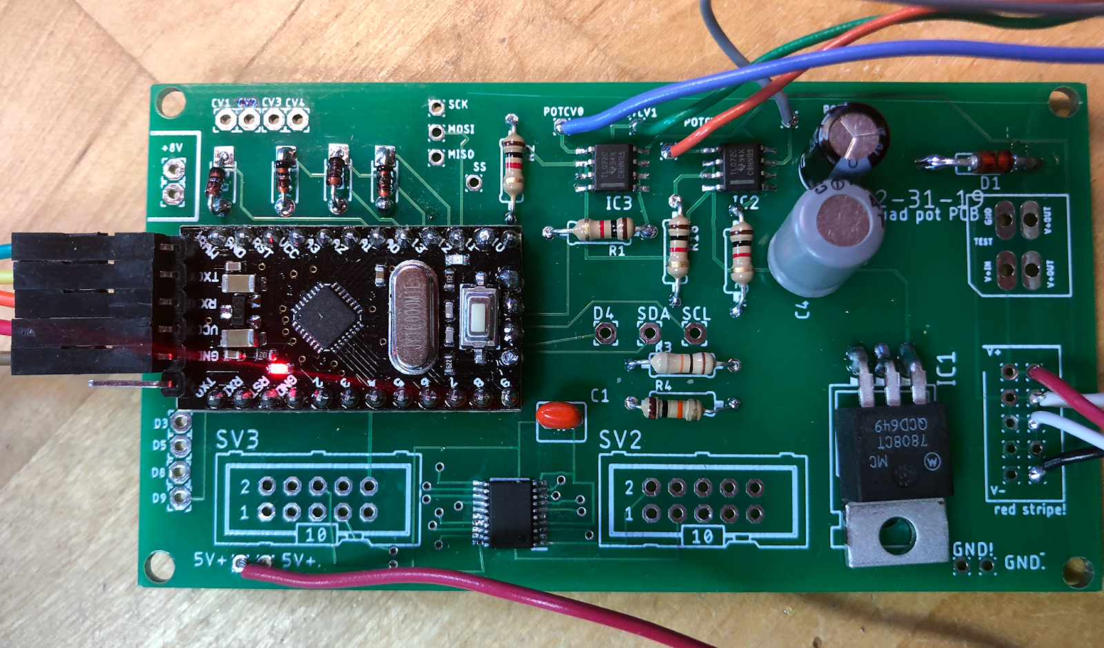
The Arduino used this time is a super cheap clone Pro Mini, same thing I used in the gate delay module (here). PM clones are ridiculously inexpensive, super small, have I/O silkscreens that are impossible to read, and seem to breed like rabbits.
The first clone PM I soldered into the board above didn't work (at all!! Regulator issue? Don't know. Never will--tossed that damn thing!--No matter what i did, I couldn't upload code to the POS. Good riddance.)
The DOA PM had to be removed using my rework station (I use a Hakko FR300....very useful, a good review vid of this tool is here). Using cheapo clone #2 Pro Mini, uploads from my Linux laptop worked just fine.
Gotta love that clone crap!
UPDATE: After more bench time I found that I had at least 3 more ProMini Clones that didn't work. Same issue--the little mofos wouldn't eat code. So it's not the single Arduino clone right I already tossed right? I have a bigger issue. What is it? No bootloaders? No, that's not it. Blah blah ginger blah blah? Nope. A mystery. the odd thing is that on very rare occasions the code would upload, but then simple things like blink didn't work. Ha! After a couple of evenings of malodorous swearing, I found the issue under the microscope: The clones advertised themselves on Aliexpress as being AVR 328 based but were really 168 based. This was very, very tiny writing on the chip. Is it stupid yet?? No wonder the code didn't upload. I changed my Arduino IDE to accommodate and compile for the 168 chip and everything started to work. Yeh!
OK with that all in place, I whipped up an additional board--to contain all the pots and jacks and whatnot for the upcoming Lunetta Noise! mod project. Bench testing is easiest without CV pots floating around all over the bench right?
Tall trimmers, available from Modular Addict when I wrote this post, are used to save space. The Eagle device defs for tall trimmers can be found in the Music Thing Modular library, here. VERY useful library! Along with 3.5" M301 "Thonk" jacks, you can pack a lot of hardware into a small space using tall trimmers and 3.5mm jacks. Yeh!

Here's a quick view of the schematic and board for the tall trimmer and jacks PCB:


(The idea: I can combine these two boards with future PCBs--it all should fit behind a 12HP Euro panel, or 2u Frac, as long as any other PCB in the stack follows the 2000 x 3750 mil footprint above.)
With the pots, jacks, and AD5254 PCB all stuffed and wired up, it's time to write the sketch. This was reasonably easy--the datasheet for the 5254 looked intimidating at first because the 5254 can do everything but wash your linens, but at the end of the day the code to change the four wiper positions from analogRead() calls is pretty simple.
For me, the only hard part was getting the correct I2C master address of the AD chip itself, which I tried to figure out from the datasheet, unsuccessfully; but eventually nailed it using the I2C scanner sketch found here. BTW, with the AD5254's AD0 and AD1 pins wired to ground, the address to use is b00101100. Knew that!
OK Here is the sketch so far:
################
#include <Wire.h>
int cv0;
int cv1;
int cv2;
int cv3;
int cv0map;
int cv1map;
int cv2map;
int cv3map;
const int cv0pin = A0;
const int cv1pin = A1;
const int cv2pin = A6;
const int cv3pin = A7;
void setup() {
// put your setup code here, to run once:
Serial.begin(9600);
Wire.begin();
}
void loop() {
// put your main code here, to run repeatedly:
cv0 = analogRead(cv0pin);
cv1 = analogRead(cv1pin);
cv2 = analogRead(cv2pin);
cv3 = analogRead(cv3pin);
//map that puppy
cv0map = map(cv0, 0, 1023, 0, 255);
cv1map = map(cv1, 0, 1023, 0, 255);
cv2map = map(cv2, 0, 1023, 0, 255);
cv3map = map(cv3, 0, 1023, 0, 255);
Serial.print("value for CV0:");
Serial.println(cv0map);
Serial.print("value for CV1:");
Serial.println(cv1map);
Serial.print("value for CV2:");
Serial.println(cv2map);
Serial.print("value for CV3:");
Serial.println(cv3map);
Wire.beginTransmission(0b00101100); //tricky. address ignores LSB and pads with 0 at MSB. Eventually nailed with I2Cscanner sketch
//consecutive write mode: n, N+1, N+2 etc bytes are now sent to wipers
Wire.write(cv0map);
Wire.write(cv1map);
Wire.write(cv2map);
Wire.write(cv3map);
Wire.endTransmission();
delay(200);
}
Ha! It worked!! The only issue I had was I forgot to add a wirepad to the pots-n-jacks PCB for ground. Doh! This was easily fixed by soldering a kludge wire from ground on the pots board to one of the ground terminals on the jacks board. OK with that fix, when I cranked over the CV from the tall trimmer board the resistance between wiper and terminals present on the 5x2 headers varied from about 17K to 97K--this could be seen between SV2 pins 2 and 1 for instance, as well as for the other 3 "pots" elsewhere on the SV1 and 2, with a DVM. GO A'S!
I was hoping to get this closer to 0 ohms fully CCW (0V CV), but perhaps that isn't possible with a digital pot?....I should study the datasheet to figure that out, but I'm too lazy, and 17K to 97K is good enough for what I'm doing here.
 |
| Resistance varies between SV1 2 and 1, 5 and 5; same for SV2, based on the incoming CV. |
I thought maybe feeding all of this into the Pro Mini at the same time would blow something up, but it worked fine, and that meant I could have everything on the bench plugged in at once; I could test the pots and buffers, read data from the Arduino IDE Serial monitor, and tweak the Arduino sketch simultaneously, all without smoking Doepfer.

OK, bottom line--I have a working quad pots board!
Next time: let's finish modding the Lunetta Noise! module once and for all. More about that soon, it's on the bench now and almost ready to test. I will probably add a mux board to it as well, which is taking shape as a more grandiose version of the CV controlled 4051 module here. The goal is to add to the CMOS madness, I want this thing to sound very, very weird.
Onward.
In the meantime I recommend getting your hands on some ICs, write some code, and have fun with your quad pot, but don't breathe the fumes. See ya.
UPDATE 2-26-20: this quad pot thing has been married to a Lunetta Osc board and works! See the post here.


No comments:
Post a Comment