This time we finish an I2C slave design that gets unsigned long (32 bit) values to show up on a 7 segment, 6 character retro bubble LED display.
The basic idea: use an Arduino Pro Micro to receive the I2C slave data and get the bubble display to show the 6 digit number sent to it.
Part I: I get the bubbles surplus (National Semi NSA1166--but the ideas here can probably be used on most any bubble or 7 segment display) and get it working with an Arduino, here; how to get the 32 bit long data needed--from one Arduino to the ProMini on the back of the bubble board, here.
This time I created a PCB for the Pro Micro, 74HC595 shift registers, a Bourns SMD resistor array and the bubbles--and it works.
Not that much to say--feel like I've met the goals.
The basic idea: use an Arduino Pro Micro to receive the I2C slave data and get the bubble display to show the 6 digit number sent to it.
Part I: I get the bubbles surplus (National Semi NSA1166--but the ideas here can probably be used on most any bubble or 7 segment display) and get it working with an Arduino, here; how to get the 32 bit long data needed--from one Arduino to the ProMini on the back of the bubble board, here.
This time I created a PCB for the Pro Micro, 74HC595 shift registers, a Bourns SMD resistor array and the bubbles--and it works.
 |
| Notice yellow kludge wire; I screwed up one of the pull ups for the 74HC595's on Rev1 6-14-20 of the PCB. I'll fix that and post on my website. The chip on the far right is a Bourns 330 ohm SMD resistor array. |
Not that much to say--feel like I've met the goals.
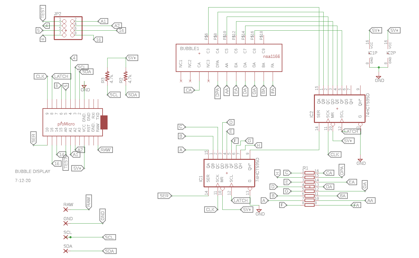
The ProMini on the board above decodes the incoming I2C. I could have used some sort of dedicated I2C or SPI latch to BCD chip or whatever, but this way I have an MPU already good to go if needed--useful if I want to repurpose this board to be a part of a clock, sensor readout device etc.
One of the trickier things here is the bubble device for Eagle had to be created from scratch, as I couldn't find it in an existing library. Also the Eagle bourns resistor array eagle footprint had to be modified as the pads were too small. For anyone who still uses Eagle vs. Kicad, a good tutorial on Eagle device creation and modification (from technically dazzling righto.com--truly awesome stuff) is here.
Oh yeh I had one trace error which I fix here with a 30 gauge kludge wire; website has this correction already.
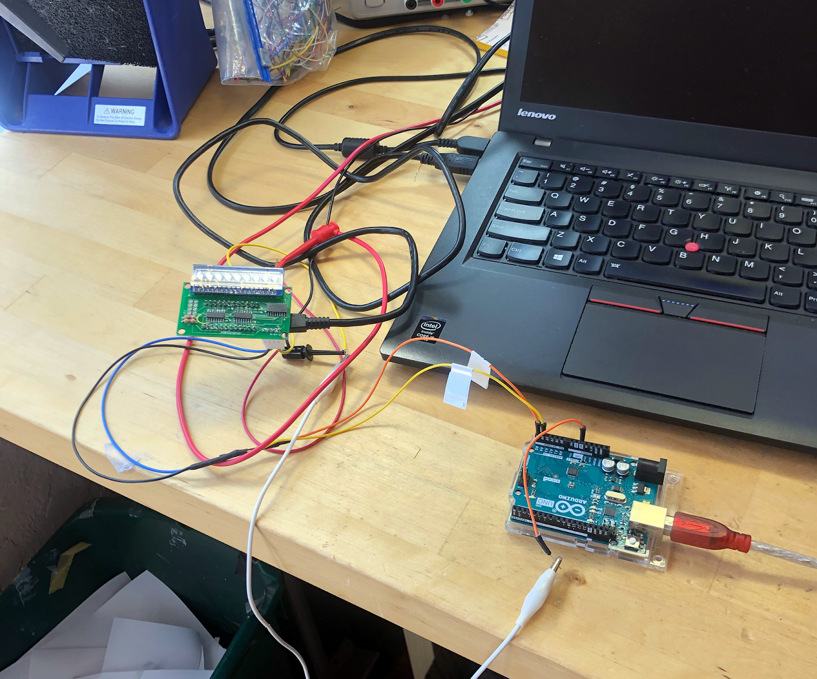 |
For tests, Uno as I2C master and Pro Micro on bubble board as I2C slave.... |

Building the bubbles: the damn thing didn't display the right numbers until I realized my code was sending bits to the shift registers in the wrong order! No, the ons and offs need to arrive at the 74HC595's in the right order for this to work. As soon as I figured that out, everything was OK.
 |
| Flip the display over--ProMicro! |

What will I use this I2C retro bubble display for? No idea. I was thinking visual frequency output for a VCO? Pulse timer? Countdown display for something or other? No se. But now that I can use an I2C device as a master for it, I have a lot of possibilities; always good.
This weekend I'll post schematics, PDFs, sketch code, BOMs etc. on my website. Update: DONE! go here. I feel an antique computer project coming next? Teensie audio? Finish the noise! project? Too much to do....
Until next time: don't breathe the bubbles.


No comments:
Post a Comment