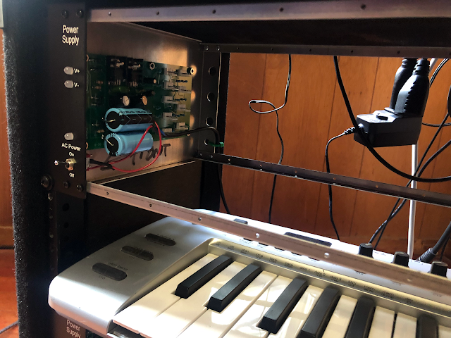
Quick One this Time: I usually build in an unusual format: PAIA Frac. It uses +/-15V (not +/- 12V/5V found on Euro). Physical Size is about the same, but Frac generally does not require "skiff" configuration, making it easier for prototyping, DIY and quick modifications of whatever you're conjuring up.
However there is a drawback to Frac: PAIA's 9770 series "wing" frac linear supplies are a bit wimpy and hard to work with. So a while back I built a drop in replacement. (see the post here)
This time let's further improve on the "improved" clone replacement.
Size Matters: The original PAIA supply as well as my drop in clone are small little squarishy thangs, each with 5x +15/-15 DC connectors for your modules. Right away that's a problem: we need more power headers, because a standard FR-7 frac case can hold up to 10 1U modules--load it up all the way and we'd be 5 connectors short.
Also, The original 9770R has no PCB provisions for heat sinks for its regulators--and the regulators on the orig 9770R swing in the breeze; if you add heat sinks to the PAIA board they could cause shorts. Let's fix that.
Of course you run the risk of sucking too much current out of the supply if you hook all sorts of current drawing craziness, but we need to be able to source at least 130mA+ from each rail of the clones without too trouble; and maybe a lot more; so let's make sure to use heat sinks and thermal paste for best performance.
(BTW, PAIA did address some shortcomings with the beefier frac supply which at the moment I can't find on their site--did they discontinue it? Assuming it's still in production it still has "regulator flap syndrome" (glue em down boys!) and takes up 1U of your FRAC case. This potentially makes the power header connectors hard to get to, depending on what you have mounted adjacent to it, so i am back to the clone of the clone. Still if you can find it and physically protect the on board regulators it's a good supply.)
 |
| New Psup board top; original drop in clone bottom. |
 |
| Almost ready to test: the new PCB mounted in an FR7 enclosure. |
Some would argue that a lot of the smaller filter caps here don't do squat, and maybe even some of the larger filter caps could go away and you wouldn't hear a difference, but linear audio guys love filter caps right? I have a bunch surplus so I threw 'em on there.
Yes you need to dig up 2x more 4-40 screws, spacers, and some nuts, and will have to drill out 2 small holes in frac side case panel. The stretch board has 6x mounting screws, where the original had 4x. But overall it's easier to plug in modules and you get better physical support for the far side of the PCB.
All in all, seems to work; I've built 2 of these "stretch" supplies without issue. Of course, as with any electronics DIY project--be careful. something as simple as putting a polarized cap in backwards can cause big problems, so work slowly, and if you're not sure what you are doing, get help.
Time to move on!
If you want to check out this p-sup--get PDFs, schems, gerbers, BOM etc, at my website here. You'll need a beefy AC wall wart as well; For each supply board I used 16V AC 1A wall wart that I got surplus and it works fine.
Until next time: Frac well and live.
 |
| "Seems working" |
All in all, seems to work; I've built 2 of these "stretch" supplies without issue. Of course, as with any electronics DIY project--be careful. something as simple as putting a polarized cap in backwards can cause big problems, so work slowly, and if you're not sure what you are doing, get help.
Time to move on!
If you want to check out this p-sup--get PDFs, schems, gerbers, BOM etc, at my website here. You'll need a beefy AC wall wart as well; For each supply board I used 16V AC 1A wall wart that I got surplus and it works fine.
Until next time: Frac well and live.


No comments:
Post a Comment