Hello again! A few years ago I designed and laid out an Oberheim SEM inspired attenuverter, posts are here and here.
Never being 100% happy with anything I do, I redesigned the main board to give better user control of bias inputs. Today's post goes over the updated circuit design.
 |
| Improved attenuverter module in FRAC format |
Let's look at the bias input buffers found in the initial design:
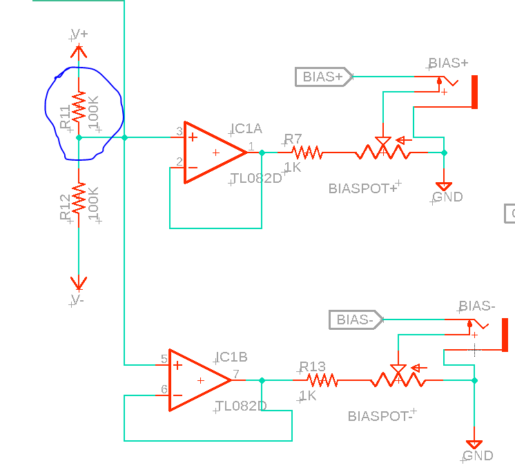 |
| Original design |
First off, the 2018 design has a glaring typo: pins 3 and 5 need +5V at input, not 0V, so I don't know what I was thinking with a 100K/100K voltage divider between the rails. I used 47K for R11 in the actual build, but still, the circa 2019 schematic had this glaring mistake.
 |
| Update!! |
Besides fixing R11's value, the Bias pots now control levels found from the CV **or** the signal found at "Bias+" and "Bias -". This meant the user has greater flexibility for controlling the input bias CV using the B100K pots.
The rest of the schematic remained unchanged.
Another issue was that the PCB was tall to comfortably fit into a Frac case. This is fixed in the gerbers found on the PCBWAY project page, here, and the github for the build, here. If you want to build this attenuverter for Frac, make sure to download and fab the standoff daughterboard for the CTPOT, it is needed for the layout.

With the PCBs trimmed to size it was now a matter of populating it.
.png) |
| The latest Attenuverter PCBs were provided by this blog's honorable sponsor, PCBWAY. I would be very grateful if you could check them out for your next project. |

 |
| A daughterboard is needed for the center tap pot--read more in this previous post. |

 |
| The center pot shaft had to be shorted using a Dremel tool. |
 |
| ready to test! |
 |
| I like it when it works the first time! |


No comments:
Post a Comment