I have a few days off for the Thanksgiving Holiday. Time for more DiWhy fun!
Doepfer smokers: this time I completed a EuroRack analog LFO design from my distant past--"LFO Prime".
For more about the features and development of this LFO check out the previous post here. To summarize: I cobbled together different LFO designs back in 2002 or so, into this module, but didn't document anything. It took me a bit to figure out how the 2002 era circuit worked, but I did, and this is it.
I figured the build would work without issue and it did....since I already built this same circuit for Frac and large format.
Let's build!
As they say at the dentist's office: "you know the drill".
I laid out the boards on a Windows PC using Eagle CAD, then shipped gerbers off to PCBWAY (this blog's trustworthy sponsor) for quick fab.
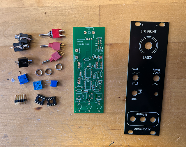
The boards came back posthaste:
Unbagged them and inspected. Looked good.
 |
| Front panel and main PCB for a "skiff" (<30mm depth) module layout |
 |
| Rounded up the parts.... |
 |
| From here it was like building a kit....my calculation: +/- 12V Euro power should work without issue.... |
 |
| I put the C3 and C4 caps and the trimmers on the back of the board. |
 |
| Ready for final assembly and testing |
 |
| "Seems working!" |
I experimented with different values for the speed pot (A25K was best--higher values for this component led to issues with the symmetry of the triangle wave at output) and "speed" caps C3 and C4 (ended up using 47uF (range = "fast") and 1000uF (range = "slow"); if you build the LFO you may want to experiment with the values of these two capacitors.


No comments:
Post a Comment