Sunday, April 2, 2023

Bench Mixer: Stupid Mistackes

Back in analog-land: time to replace a Frac bench panel with something more high class.

Panel on the left passively converts 3.5mm jacks to 22-ish gauge binding posts connected to a power amp. Top notch aethetics, right?

The old board, built from a frac aluminum panel, worked, but was butt-ugly.

Let's redo this in Euro

I figured I might as well throw in a mixer while I'm at it. 

Easy right? This is a couple of non-inverting op amp mixers. I can lay this out in my sleep! It will work first time!

Nope.


The idea: have independent mixing for left and right outputs with some normals to handle mono inputs:


Bing, bam, boom! Designed in Eagle....created gerbers....got the boards back pronto from this blog's patient and highly enthusiastic sponsor, PCBWAY:


Happiness is new boards from PCBWAY! Please help this blog and check 'em out.

The project was centered around dual contentric pots (you can get these from small bear and other DIY vendors), but I could only find these in 90 degree variations, not 180 degrees. So, not a slam dunk for Euro skiff, which has to not exceed about 30mm in depth. 

I might try to lay out a skiff-friendly adapter for these handy dual concentric pots, but this time I ended up side-mounting the PCB:


Once ready to test I used two "con-244" 100mil connectors from All Electronics, soldered back to back, to connect the jacks PCB to the mixer PCB:

Why is it not fully soldered? D'oh! Keep reading....

When ready to test the module looked good!


One big problem--it didn't work!

At first literally nothing; no audio at output. I hate this! But why scotty why? Turns out, the pots were wired upside down! So CCW rotation turned the volume all the way up. CW turned it all the way down. Very nice.

What's wrong with this picture? 

(HONK!) For volume to go up when you turn the knob up, the arrows have to go up!  

There is another problem here.  See that "in 2"?  It needs to be connected to the right channel so L1 and R1 come out of the correct output! Missed that too.


More issues! The drills for the output wire blocks were too small!  Easily fixed? Just jam 'em in there anyway and solder, right? Nope. I tried that, and what you see here "worked", sort of, but, felt flimsy and probably would have failed eventually.


It got worse! I forgot to wire ground from the main board to the jacks board.  "Who needs ground"?


Nice kludge wire for ground

Also the L1, R1, L2, R2 wires from jacks to main board were out of order. I tried cutting and rewiring the 4 conductor jumper but about halfway through I realized: too many stoopid mistackes, too many kludges, shut up n' redesign the damn PCBs.
Overall this was a huge fail. I thought this was going to be an easy build and rattled off the design with way too little forethought.  

What now?

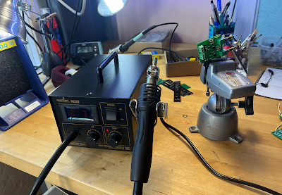
The grim reaper of DiWHY?--sparkfun air work station

Get out the hot air! I removed any parts I figured I could reuse on the next iteration; the PCB goes into ewaste:


...and then redrew the boards to fix the mistakes.

Improved jacks board with a ground!

So back to PCBWAY for another go around.  

Time wasted: two evenings.

I'll keep you posted.  Until then, don't breathe the fumes.  Update: rev 2 works!  Post is here.

No comments:

Post a Comment

Son of Anything To Clock--LM311, Lower Parts Count

Readers:  If you want to build the project featured in today's post, please go to  PCBWAY's  Community pages --a gerber ready to dow...