Hats off to this blog's sponsor, PCBWAY....check out their Community Page--clicking those links lets 'em know I have readers, which helps me create new projects. Thanks!
==========
This time I continue to clone or knock off subcircuits from the legendary ARP 2600 synthesizer. From my patient sponsor PCBWAY I recently received an ARP 2600 inspired synthesizer preamp PCB I laid out. Let's see if my design works or is butt.
But first, here's an incredible (?) piece of luck....I was walking around my neighborhood the other day and in a sidewalk box bursting with "Covid Pandemic--Free Stuff!" found an almost new-in-box Radioshack/Realistic dynamic microphone circa 1970 or so:
 |
| USD $9.95! Hi-Fi Response! 10K impedance! |
The box was a bit worn but the mic inside seemed to be good as new....being period correct and all, I will use that to test my preamp.
 |
| The mic terminates in a 1/4" plug; I used a 3.5mm cable adapter. Can't beat FREE. |
ARP's design is a single op amp stage with a 3 way switch to select x10, x100 or x1000 boost by choosing different resistors in its negative feedback loop.

I know (knew?) zilch about mic preamp design but digging around the Internet: using op amps for the gain stages was an easy way to go.
I figured the hardest thing was finding a "Range" 3 or 4 position toggle switch I liked. After a bit of thought I decided to have each output signal (x10, x100, x1000) have its own 3.5mm jack instead of using a switch. This took up more space but was simpler to lay out.
I also decided to provide a cap-coupled AC input and a DC input; the ARP is capacitor coupled only. The DC input would be normaled to break the connection to the AC input if used.
Furthermore, I brought a x1 output to patch to use as a unity gain buffer.
You can get the original schematic for the ARP preamp here (go to page 11). It's a pretty simple single op amp design; ARP used a Teledyne 133901 op amp with some clever resistor switching to get different output levels.
I took a different (and I think, simpler) approach to ARP's; I used 4 op amp stages in series:
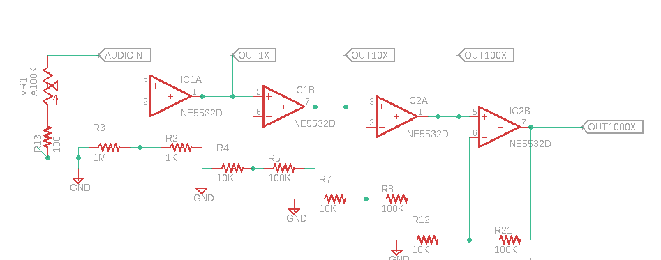
The rest is power and jacks...."keep it simple, stupid."
 |
| New boards from PCBWAY.... |

 |
| SOIC op amps were used to save space.... |

 |
| Ready to test.... |
 |
| I found .1uF filter caps for the op amps to be necessary to get rid of a bad buzz at the x100 and x1000 gain outputs. |
When I first powered up the board it acted strange--the 10x output seemed too "hot" and the 100x and 1000x outputs were slammed against V--.
After looking at this for a bit I realized I used the wrong values for R5, R8 and R21--specifically 1M instead of 100K, the extra zeros pushed the circuit into impossible amounts of gain--making the op amps do crazy things.
With the resistor values corrected the circuit worked and sounded OK, even with my big dude RadioShack Realistic 70's era microphone. Didn't sound great--a lot of hiss and noise--but....OK.
 |
| I also made my first microphone for the project--a surplus dynamic mic element (Triad 1D1P 14R06C), cable tied into a plastic gum dispenser with some foam rubber shoved in for good measure. It worked, but sounded--well, crap. Maybe it sounds so bad it sounds good? Things can only get better. |
Am I done? I was going to lay out a front panel, stick it in front of this PCB, put the gerbers etc. up on PCBWAY's project page, put it in my rack, and call it a day.
Then realized if I ever wanted to experiment with low noise design techniques: this is the project.
To that end: in the next few weeks, I will try different things--lower noise op amps, 2 sided ground pour, better power filtering, ferrite beads, etc., to see what if anything makes a difference.
 |
| Make me proud, son! |
Of course the freebee mic may be the source of some or a lot of the noise.
Assuming the upgraded design sounds better than what I built today, I will upload that to PCBWAY's project page, post the schematic, include a BOM, and so on, the usual thing.
Update: rev 2 Arp 2600 inspired preamp is done--post is here.
Until then, don't amplify the fumes...


No comments:
Post a Comment