If you're interested in a DG401 experimenter's board--hear this useful analog switch IC for yourself--go to this blog's sponsor, PCBWAY....check out their Community Page....download the gerber for the PCB discussed in this post here. Have fun!!!
==============
So whattzup.....this morning I am at the bench creating a work-alike for the Electronic Switch in the legendary ARP 2600 synthesizer.
For a background for the project skim the previous post here.
I wired up the toggle flip-flip and buffer breadboards from last time to an experimenter's PCB centered around the DG401 CMOS analog switch IC--the board courtesy PCBWAY.
With everything wired up I could hear the DG401 switch between >10V P/P waveforms. Works!
 |
| DG401 test rig: works. Clockwise from left: DG401 experimenter's PCB, Siglent test gear dookie, the T-flip flop breadboard and the buffer breadboard. |
Here's the signal flow for the test:

A clock signal (from my Siglent signal generator or a bench Euro LFO--didn't matter) went into the buffer circuit described last post:

This feeds the Toggle flip-flop:
 |
| I found the circuit worked better with 6-8V to pin 16 of the CD4027.... |
The flip-flop's two outputs--basically a square wave and its inversion--go to data IN's--DG401--pins 10 and 15:

For S2 and S1 I buffered the incoming audio (or CV, up to you) with a unity gain op amp; for output pins 1 and 8 I mixed pins them together using a standard 2 op amp non-inverting summing mixer.
 |
| Basic idea: non-inverting summing mixer....to compute gain, get resistor values here. |
The experimenter's board also had an external clock to logic subcircuit....get a simulation of that here.
The circuit fragment below was not needed for the experimenter's board but I threw it in anyway. It allowed an external clock signal--say an LFO's square wave--to be split into a logic high (A) while (B) is low, then visa-versa on the next clock edge--the same idea as the output of the T flip-flop. 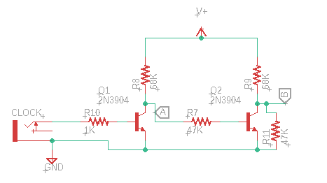
However, the CD4027 and its buffer seemed a bit more tolerant of unusual (?) signals to activate the switch; for the final build I will probably use the flip flop, even though it requires more components.
Here are some useless build photos:
 |
| Happiness is new boards from PCBWAY! |


So how did the DG401 sound? Well.....GREAT. The DG401 switched super fast, no audible clicks, pops, or oddness. Remarkable, really. And you can still find it for sale in P-DIP....and it's not too expensive....
In terms of making this switch switch--I had to do what its datasheet says--S and D are normally disconnected, to make them connect hit the logic pins ("In") with >= 2.8V.
This meant I needed to power the CD4027 with >6V or the CD4027's "Q" output was a bit too low.
So what's next? I will make all the parts so far into a compact Eurorack synthesizer module. One of these days....Stay tuned for Part 4.3. Update: Done! Works! Post is here.


No comments:
Post a Comment