Readers: If you want to build the power expander featured in this post, please go to PCBWAY's Community pages--a gerber ready to download and/or fabricate as well as KiCAD files, stl for 3D printing, FreeCAD files, and so on, are here.
Also please visit PCBWAY's site using the link here--it will help this blog. Thanks.
======
I had so much fun getting started Kicad, why stop there? I needed to replace my 3D app of choice--Fusion 360--whose license fee will go up by >700% in a few years--same as Eagle's--with something more affordable.
After looking around I chose FreeCad, a popular open source choice for 3D modeling.
As my first FreeCAD project I created a tray for the Improved Warm Floater (initial post here)--the Warm Floater is a small PCB allowing 3 Euro modules to be powered by a single 16 conductor ribbon.
The improved floater circuit board employs box headers in an effort to make it nearly impossible to orient the power cables incorrectly.
I needed to create a tray for the PCB, insuring its contacts can't short against a conductive surface.
How did it go? So-so. Freecad is a complex program with a complex user interface; you won't be able to use it without a fair amount of study and practice.
After a few evenings I got it working--fortunately there are almost endless youtube tutorial videos about FreeCad, although FreeCad's UI has changed over the years, so I had to refer to newer tutorials.
And I needed to remember: FreeCAD is free. No whining!
FREECAD WORKFLOW
 |
In Part Design I create(d) a body then create(d) a sketch" (links were on the left side of the screen).

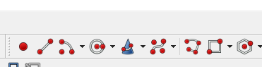 |
| I found FreeCAD's icons to be confusing. For instance, here are 2D sketch tools. The rectangle and circle are obvious; The dunce cap? I still have no idea what the hell that one does. |
Once I had my rectangle, I had to constrain it. I was unfamiliar with "constraining" my sketches, this meant, locking down the 2D proportions.
 | |
| Dof!! |
Constraining the shapes for my simple tray was easy enough however and after some practice constraining simple 2D shapes became pretty quick. Update 7-12-25 for version 1.01 of Freecad you get at the basic constraint tools with an icon I hadn't seen before:

Clicking the down arrow you can see tools to constrain vertically, horizontally, set the radius or diameter of a circle and so on.
Once constraints were set, I clicked on CLOSE which closed the sketch and brought me back to the "part design" workbench. A handy sketch tools dialog appeared, with choices like pad (which meant, extrude); hole (which allowed for tapered screwholes) and so on, but if I clicked anywhere else in FreeCAD this dialog went away and didn't readily come back....

....fortunately the same actions were found as icons along the top menu:

The next thing I did to my 2D shape was pad it (extrude it upward in the positive Z access). OK, I padded to 3mm.
Next things got tricky.
To create the tray I had to create a second sketch inside the first sketch, then"pocket" my design, "Pocket" is another FreeCAD term that was new to me.
This wasn't how I assumed you'd do this, why not have a command "make a lip" or whatever, but, nope. Every shape/cut/extrusion/screw hole in FreeCAD needed its own 2D sketch.
I thought I could create this inner sketch by clicking the sketch icon in the main menu and creating another rectangle--but--nope.
The 2nd sketch appeared to be hidden by the first. Drat!
I couldn't see this second sketch until I viewed the part from the bottom....that's where sketch 2 was created, BELOW the original one (not what I would have expected, nor what I wanted).
What I need to do instead was choose the topmost plane of the initially created sketch by single clicking it.
This "surface selection" (my term) only worked for creating additional sketches when the plane was the only thing colored:
 |
| Very important to make sure the surface I wanted my new sketch to sit on was colored, as you see here. Otherwise the new 2D sketch didn't appear in a useful manner. |
Now if I created a new sketch its Z origin sat on the green plane. Ah, that's what I wanted!
I created the inner sketch then constrained it to be exactly 1mm inside the first (is there another command "make the new sketch 1mm in every direction smaller than the one I just drew"? There must be....)
Finally clicked on a line of the inner sketch and clicked on the "pocket" icon. I chose a "dimension" pocket which was the default.
I entered 1mm and it worked.
Next, I needed 2 holes in the bottom of the tray.
When I tried adding the 2 holes to my first sketch I discovered once again--everything in FreeCAD with different Z extrusions had to be its own sketch and must sit on the correct plane.
I created a 3rd sketch, again choosing the surface I wanted the new sketches to sit on.
This third sketch consisted of two constrained 3mm circles that would form the holes used to mount the PCB to the tray using nylon screws and nuts.
Following the process above I "pocketed" the circles to push them though the inner tray (Sketch 2).
I found no other way to do this, and this seemed like a whole lot of steps, that had to be done in exactly the right order, to make what I felt was an extremely simple 3D shape.
But, it was done.
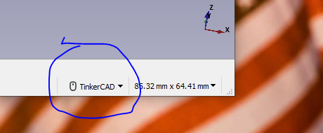
VIEWING THINGS IN FREECAD
EXPORTING 3D MODELS TO KICAD

TURNING THE DESIGN INTO TRAYS
With my tray finally done I printed one of these out on my 3D printer--which worked!--but needed more of them.


Let's build!


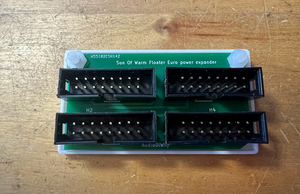 |
| 3mm nylon screws and nuts fastens the PCB to the tray |

This got mounted in my bench rack, now I can put more modules with low current draw in there....much needed improvement.
I figure I will get better at Freecad over time....this still feels very new to me.
See ya next time.


No comments:
Post a Comment