Friday, December 27, 2019

All Hail the Mighty MR. LABEL--Easy and Cheap Front Panel Art

If you've been following this blog you've seen me post lots of stuff about front panel fab. How to make this look pro?  I've posted about Lazertran (a decal process) and Front Panel Express (send them art and a bunch of money and they send you back professional looking finished panels), but also p-touch, sharpee, rocks and chisels....

Seriously I have found a good product for this, way easier than Lazertran and way cheaper than FPE. And it has a fun/dumb name: "Mr. Label".  And the results look pretty damn good! I guess DIYers have been using variations on this for decades and I am just getting to the party? Better late than Never right?

Mr. Label doesn't dress up--it comes in a unremarkable plastic bag.

Mr. label: Not to be confused with "Mr. Horse"?


Where to Mr. Purchase: You can get Mr. Label from Amazon (of course); Spumco I mean MrLabelCo has a butt ton of products; the exact SKU I got is this:

Mr-Label White Matte Waterproof Vinyl Sticker Paper - Full Letter Sheet Label - Inkjet/Laser Compatible - for Home Business (10 sheets/10 Labels)


Not sure this link will work in six months, but on Amazon it's here.

Meet Sr. Etiqueta: Mr. Label is stick-on vinyl sheets you can run through your laser printer; you then cut it out your design and carefuolly stick it on your front panel, finally, coat the panel with clear spray paint. After only about 1/2 hour of messing with it, I found that Mr. Label is pretty easy and super fast to use, and looks good--not as fully pro as FPE, but much better than some of the Lazertran work I've done over the years. For most everything synth DIY dudes do, I think the respectable Mr. Label is good enough.

And! It's relatively inexpensive--$8 USD for 10 8x11" sheets. Compare this to Lazertran which is more like $3USD a sheet, and FPE, which is about $42USD for a 1u Frac panel.

Conceiving Mr. Panel: Before you begin, read Mr. Label's included instructions--yes, Mr. Label will dry out if you don't bag it, yes, Mr. Label may get the runs if he eats too much Inkjet--although Mr. Label advertises as "works with Inkjet"--aka Mr. Laxative?


Whatever. I don't use Inkjets so I can't be sure. But on my B&W laser there were no runs, no smears, no issues.

OK let's do this. First, do your metalwork. From previous posts, I use PCBWAY in China to fab my "alubase" panels--you can send them gerbers and they send you precut 1.6mm aluminum panels ready to use. For maybe $2-4USD per panel. Yeh!

Now prepare your artwork using your favorite art software--I use Illustrator and Photoshop, but there are a ton of programs out there that will work just fine.


Hint: Print out your artwork on normal paper to make sure it's good to go. I usually hold my paper up to the light with the panel behind it. Are the holes in the right place?  Is the overall size OK? You get the idea.

Now print your masterpiece on a sheet of Mr. Label:

If I didn't use tray1--the manual feed tray--on my HP 402DN the honorable Mr. Label becomes his sinister alter ego: "RapMaster Tray-Jam". So get ready to experiment a bit with this and remember: if your printer jams repeatedly, swear like a mofo.


My HP LaserJet 402DN is a pretty low-end, simple HP black and White Laserjet. To me that means you don't have to use a fancy printer to get this to work. I have to use the "extra heavy 135-175 label" setting and feed the vinyl through the manual label feeder ("Tray One") on my printer, or else the thing jams the printer, but that's what the label feeder is for, right?

Ready to stick!


Hint: It might be hard to tell which side of Mr. Label to use--the backing and vinyl look the same, so I fingernail the corner to figure out what is what.

After printing--carefully--VERY carefully--for me this was the only hard part--align the label with the panel and stick it on.

Then brush out any air bubbles from inside to outside. Next, use an x-acto to cut out any drills (doesn't have to be perfect cuts--the jacks and pots will probably cover sloppiness.) You get something like this:


Last step is to spray it with clear topcoat.  I used this one. I'll bet acrylic spray clear coat will also work, maybe work better than 2x Ultra Cover which is the first thing I grabbed at a nearby auto parts store.  UPDATE: Since writing this post I have tried different clear coats to spray over Mr. Label--acrylic artsy fartsy, enamel model plane spray, etc. The RustOleum paint below, that I happened to grab initially because it was the first one I found in the car parts store--still works best to date. Go Figure.


The results were remarkably good, and these were two first tries.


OK time to make more panels! Mr. Label is Mr. Recommended. I keep thinking my relic 1970's Mini doesn't look like it uses silk screening, looks more like some sort of vinyl process to me, and you can't get much better than that. Maybe I'm breathing Mr. Fumes? See ya after the new year.


Thursday, December 26, 2019

Vactrols Controlled by Arduinos Part II--Linear? Nope.

Hello again, from last time, can we unlock the mysterious non linearities of Vactrol/optos with the help of an Arduino?


After a few days at the bench, the answer is a qualified "probably not".

What you can do:
  • You can use PWM to get different resistance values out an opto coupler aka "Vactrol" aka "vac". See the last post about this here. From that post: if you want to control a VAC with an MPU, PWM is a good way to do this.
  • You can sweep through PWM values, at least lower resistance values, and record the steps into an array. The Vac will mostly behave.
  • You can then do math and look ups on the array to change the VAC's behavior.
But the main problem--the deal breaker?--is the same thing that always made VACs hard to use, and something we already knew: the damn things lack linearity big time, especially when fed with low current, yielding high resistance values. 

OK, After a grueling (?) + frustrating (!) 4 or so days messing with this, I mean for hours each day, my conclusion: there is way too much variation in the high-resistance range for the vacs I tested for them to ever behave in an useful, linear manner. This makes Vacs poor candidates for linear applications requiring resistance values above about 100K-200K. 

Sorry.

If you want to mess with this--feel free to prove me wrong, please! read on:

Uno PWM-VAC madness.....

OK, first thing to do is to make your Arduino into an Ohmmeter, preferably with a good degree of accuracy. There are a lot of posts on the web about how to do this, an easy to follow vid is here, while the most in depth pdf I could find on the subject is here.

But let's make it harder OK? I tried for two frustrating days--and I mean all day, for two damn days, to get this ohmmeter idea working on an Expressif ESP32. ESP32's can easily be set up for 15 bit PWM with a lot of easily adjustable parameters, and 12 bit A to D conversion. This makes it a perfect candidate for this project (it's also much faster than any Arduino I've tried to date).


But I couldn't get the ohmmeter part of the project working on an ESP32 with any degree of reliability. Eventually I gave up. CRAP.  I couldn't get anything better than about 80% accuracy for ohm readings, best case, and most often way, way worse. Even for 1K.  Even for 10K, even for 100K. Forget about reading vacs--that's trying to read normal resistors, using my tough-n-ready Fluke 117 to A-B what the ESP32 was coming up with. Nope, don't like it. Not one bit.

With an Arduino Uno, I could easily get 1-2% accuracy to about 100K or better just slapping in parts.


Greatest thing since sliced bread--so how come simple Ohmmeter sketches didn't work?


So I used an UNO with PWM set to 256 steps and the 10 bit A-D pot.

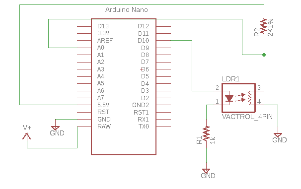
Basic hookup is this:

I used an UNO on the bench, not a Nano, and V is 5V not 5.5V.  Whatever.....


Here is the code:

//initialize pins
const int voltRead = A0;  // Analog input pin that senses Vout--used for ohm conversion


//initialize ohmmeter
int voltValue = 0;       
float Vin = 5;             // Input voltage
float Vout = 0;           
float buff = 0;
float buff2 = 0;
float Rref = 2000;     // Reference resistor's value in ohms 
float R = 0;                          
float R1 = 0; 
float R2 = 0; 
float R3 = 0;  

//pwm stuff
int x = 0;
const int pwmPin = 10;

void setup(){
  
  pinMode(voltRead, INPUT);
  pinMode(pwmPin,OUTPUT);
  

  Serial.begin(9600);  //breakfast serial

}

void loop()
{

  for (x=0;x<256;x++)
  {
    
  analogWrite(pwmPin,x);
  
  voltValue = analogRead(voltRead);  
  
  buff = (Vin * voltValue);    
  Vout = (buff)/1024.0;


  R1 = (Rref * Vout)/(Vin - Vout);


  voltValue = analogRead(voltRead);   
  Serial.print("analog read is : ");
  Serial.println(voltValue);
  buff = (Vin * voltValue);    
  Vout = (buff)/1024.0;
  Serial.print("x is: ");
  Serial.println(x);
  Serial.print("Vout is: ");
  Serial.println(Vout);

                  
    R2 = (Rref * Vout)/(Vin - Vout);
  
  voltValue = analogRead(voltRead);  // Read VAC voltage divider
  Serial.print("analog read is : ");
  Serial.println(voltValue);
  buff = (Vin * voltValue);   
  Vout = (buff)/1024.0;

                 
    R3 = (Rref * Vout)/(Vin - Vout);
  
  R=(R1 + R2 + R3)/3;
  
  delay(1000);    

  Serial.print("Resistance read: ");                  
  Serial.println(R); 
  }
}
//=================

(Yes I know the analog read thing can be made into a function vs repeating the code 3x. I'm too lazy. You do it.)

And yes, you get better readings if you change out the reference resistors to say 1M when you are reading high VAC resistance values. A good article about using a 4066 for this is here;  uh-huh I tried a CMOS switch for autorange; even with 300K to 1M reference the values read from the vac above 150K-300K bounce around like a coked up hamster on steroids--not usable nor stable. Reading a 1M resistor in this setup--yes. Accurate. Arduino Ohmmeter works fine even with the ref resistor pretty far off!

With a Vac--nope.

How about using a DAC vs. PWM?  Tried that too! using a 4725DAC.  Easy to kludge in--info here. But--Same problem. Crappy response at high resistance readings.

OK Depending on the vac, this means we have a usable response curve from about 200K (maybe, maybe less) to about 2K, but most of the useful action is between about 10K and 2K. Is that good for your project? Probably not.

Going forward: Next thing I'd do if I were to continue this work is to put the ohmmeter values into an array, something like a[x] = R for each value of x. I messed with this too but won't bore you with all the code. If you've made it this far, you can figure the array part out.

Then the array could be sorted, you could use the map function to further goose the analog readings, or math in general could be done to elements of the array as discussed in this post.

But!!! I can't immediately think what's next for ArduinoVacLandia.

In the course of messing with this I started to think the best use case is to maybe not try to do a lookup table or a bunch of feedback to an analog pin. Instead use the PWM capabilities in an ESP32, driven by buffered and voltage divided CV; that all works. Then further tweak the incoming CV with a map function, simple addition/subtraction/division of values, and who knows what else, to get the VAC to do interesting things.

But my original idea of linearizing a vac over a large range, I think, is probably not going to happen. For that, a digital pot has got to be a better choice.

So is this the end of the story? until I bite the big one: no. I will probably revisit controlling VACs with MPUs down the road, but for now it's time to move on. I'll bet if a lot more time is spent, figuring out why the ESP32 didn't work, using a 4051 to switch between 8 reference resistors, doing a lot of math, finding some opto out there in optoland that isn't squirrely,  or whatever, yep, you can take this further.

Hopefully you have more fun than I did, because a lot of these last 3-4 days at the bench kinda sucked.


Sunday, December 15, 2019

Taming Vactrols with an MCU--Part I: The Blah blah intro, Will It Work?, and Related Ideas

All hail the resistive opto-isolator, aka "Vactrol". So slow--so unpredictably funky--so malodorous--I love these parts! It's an  LED tied to a photoresistor---LED action equals resistance. Simple stuff right?


Yes, but there is a reason you don't see optos in every VC synth circuit. Vacs are the girlfriend who plays great bass but consistently smells bad: promising, but in many ways, far from ideal.

Let's break this component down, Sergio style:

The good:


  • Vacs can take a relatively large amount of power at input and not blow up. Try that with your rare OTA or expensive digital pot (better yet, don't).  
  • Vacs can go into the M-ohm range where digital pots in my experience top out at about 100K.
  • Vacs are, at face value, super super simple. In goes current, out comes resistance.  Add a resistor to protect the Vactrol's internal LED and you have instant voltage control. Viola!
  • Which means, you can drop it right into most circuits that need voltage control of resistance, as long as you can make due with "the bad" which Lee will present next.


The bad:


  • Vacs are extremely non-linear, especially in the high MegaOhm range where their non linear nature gets downright silly.
  • Vacs' non-linearities vary from unit to unit. For vac #1, 40mA in produces10K, another from the same run/same batch resists at 15K. Mr. Yuck. 
  • That means if you need 2 VACs in a given design, you probably have to match them for best results. Think 6V6s in guitar amps or NPNs in a Moog ladder.
  • That also means if you need good linearity over a wide range, or really any sort of good linearity at all, you probably need to look elsewhere.
  • Vacs are really slow. Unlike OTAs and digital pots, you can change your voltage and it takes maybe a couple of milliseconds (or more) for the Vac to "catch up"....bad, for things like VCOs etc.
  • Vacs aren't made by the zillions, and some manufacturers have stopped making them altogether. So sometimes you have to look around to find the exact Vac you want and most often you have to make do with a part that isn't quite right.


The ugly:


  • Unless you find optos surplus or make your own, vacs can be expensive--$5USD a pop or more.
  • Physically vacs are big parts--there are no SMD versions of this I've ever seen.
  • Overall the unpredictable nature of Vacs can, in some situations, drive you, the circuit designer, completely nuts. It's not always worth it.

Want more? A really good description of a vac, from Doepfer, is here.  A previous AudioDIY post about them is here, my own Vactrol based multimode, low parts count VCF is here.

OK, Wrapping up this long intro: aaaah, the opto. Buchla's legendary low pass gate uses them, MakeNoise uses them, DIY compressors use them. I use them. If you don't use them yet, go buy a bag if you ever see them surplus, get them on your bench and do the messaround. Yes they will drive you crazy, but also, like the aforementioned punk rock bassist, hold your nose and have hours of fun.

OK without further Vacdoodoo: Here's part I of next batch of Vac-uuous--Vactaitious--Vac-trolius--AudioDIWHY posts: can we use an Arduino to tame a Vac?

Goes like this: I was lying in bed thinking about Vactrols (yes, I do do that) and figured the snot-slowness cannot be helped. But how to solve the other two issues--that one vactrol is never quite like the next, and Vacs extremely non linear. And then it hit me, bolt upright in bed: can we use an MPU to ameliorate!!!!


My thinking, in its simplest form:

  • Use a resistor in series with the Vac LED and the Arduino PWM. The LED is a current controlled part....I am going to thus treat a Vactrol going forward as a non linear voltage controlled resistor and assume we always have that current limited resistor in series.
  • Create a lookup table in the MCU (Arduino right? We all know how to program those)
  • For CV input x, find the value for X in the lookup table, and send voltage y, which will produce the desired resistance for X, to the Vactrol. 
  • The idea is that the MCU > Vac circuit fragment can produce a "corrected" resistance for the Vac, ultimately giving you something approaching linear, making it much more musically useful.
  • And if you can use a lookup table for linear, you could modify it for log or antilog as well.
Why wouldn't this work?

Next I started to think about how to get the voltage out of the MCU.  We could use an D to A IC, but to reduce parts count, let's try leveraging the PWM that Arduinos can produce.

Could it be that easy?

And a more out-there idea: we could make a second Arduino be a"table creator programmer" and then blast the lookup table created by MPU #1 into a second Arduino's lookup table. That might speed up deployment of this linearization MPU. This idea is still a bit (pun intended) "sketchy" but is still worth more digging around.

Who Needs to Work when there's AUDioWHY?

This idea went OCD on me and I almost didn't go to sleep that night but had to eventually (damn day job).

Before I got on the train, I posted on the E-M forum to see who has messed with Arduinos controlling vacs--post here--seems like that's a big no one--so let's get to work!

I did do some breadboarding the next evening to see if this was feasible.

Yeh, the basics work:

You can get the "dim LED analogWrite() test sketch--get that here--drop it into an Uno or Nano and modify the sketch to the appropriate PWM pin. Breadboard it like the schematic above.

Next, put your ohmmeter across TP1 and 2 and yes, as the PWM duty cycle changes you will see some resistor action. I got something like 10K to 40K out of one of my junk box vacs in this extremely simple configuration.

Might be useful for something right off the bat, even without tackling the lookup table?


Mildred, can I get more? It'd be nice to get a wider resistance range out of this, and intuitively I figured the Ardino can't source enough current for that.

I put aside the Arduino for a minute (why mess with more programming at this stage?) and fired up my Siglent function generator.

Next I perfboarded a very simple current booster:

Pulse in is the pulse signal from a function generator. V+ can be 15V--change V+ to  vary the resistance between TP1 and TP2

I tied the fragment above to the breadboard junk box opto:


I set the pulse frequency to 10K; used a 5V-0V pulse wave, varied the PWM as per the table below, and here's what I got:

at 4uS: 50K
8us: 30K
12us: 12K
100us: 4K
500us: 1.3K
999us: 870ohms

So we've created a somewhat decent 50K resistor here. We can't go down to 100ohms which would be nice--can't have everything but this is still useful.

I found that by experimenting with different optos, different C1 values, different pulse frequencies, and different duty cycles, I could get results in the 1K to 2M range, which might be good for something like a VC glide circuit. So in general, controlling a Vactrol from a PWM source works.

Or does it? A big problem I am grappling with as I write this post: at high resistance ranges things get unstable. The resistance from a single PWM setting jumps might around from say 1.5M to 3M.  I figure I have to improve up the RC filter above to improve this, which I will work on in a bit. Stay tuned.

Bits and more bits: Grumble aka Big Dutch Ed from the E-M forum notes that the native analogWrite() Arduino method produces only 8 bit, 256 PWM resolution, and we might want something better. He's right. We could set up 16 bit PWM for the Uno, but it's kludgy, so let's see what else is out there.

I dug around and found the Espressif ESP32. Good news--many vendors make this processor into a sort of Arduino Pro Mini on steroids by dropping it on a board, adding a crystal, pins, vreg, etc., the usual Arduino type setup. For those, it seems that the PWM pins work at 15 bit out the box. 

Wait, it gets getter: the ESP32 has 2 independent cores, Bluetooth and WiFi built in (so you could make your vactrol chooch from your cell phone?? Are you kidding me?), and its many development boards and clones of development boards can be programmed using the Arduino IDE. 

And all for maybe $10USD a piece. 

Holy IOT, Batman! ESP32 is a truly amazing bit of kit, especially at that price. If nothing else, this Arduino + Vactrol road has led me to what looks like an amazing inexpensive microprocessor I didn't know anything about before.

ESP32's. Arduino IDE ready MPU; Amazing power and features at a very, very low price. It reminds me that at our core(s), we human beings are good.


The Auto-table idea:
Final idea: how to speed up creation of the lookup table.

I don't want to have to hand-enter a lookup table each time I use a new vac. I was discussing this project with E-M member (and a neighbor of mine) MVCL and he suggested something more like this:


The idea:

  • Have D3 ouput, at start up, be a PWM duty cycle sweep
  • Capture the output of "Sense" (a voltage divider) at analog input A0
  • Use Ohm's law to compute the lookup table for linearization of LDR1 as the PWM is being swept.
  • Blast that table into on board memory
  • Turn off the table generation mode
  • Use the other analog pins for CV
  • Use the lookup table and go!
  • You could run this routine to re-craft the table at start up which would accommodate things like changes due to environmental factors.
The issue here is that A0 is only 10 bit, but still, it's a better idea than using 2 Arduinos for this. This will require more work and thought, as always, but again, this all sounds doable, and is a much smarter approach than whatever I had rummaging around in my head.

Next up: I bought some ESP32's and need to see about getting the 15 bit PWM working.  If those MPUs work as pulse generator with 15 bit PWM accuracy, I might get to building something that is musical soon.  UPDATE: 12-18-19. ESP32 works great--I followed the vid here to get one going in Arduino-land, using a cheap Amazon ESP32 board, Fedora Linux, and the current version of Arduino IDE--and yes, Andreas Speiss rules.

Many more hours of fun ahead!  Until next time, don't breathe the fumes.

UPDATE: Part II is here.  SPOILER! couldn't get an MCU to fully solve the "crap linearity" issue.  Still, this is a very useful concept, I think....  


Friday, December 13, 2019

DIY Front Panel Fun!!

Graphics time! How did I get here?

I never thought I'd do any graphic design (ever) but when you are into A-DIwhY I guess you are forced. What's an old rock and roller supposed to do? Use a Sharpie? A cardboard box? I guess that works. But I am finding with the right tools and time to kill, even for someone like me with a really crappy eye, front panel design is hours of fun.

How I do it to date. You've heard of good-better-best?  I have crappy but works ("CBW"), "A-OK", and "pretty good".

"Crappy but works": I order "alubase" blank front panels from PCBWAY in China and then use Brother P-Touch tape for legends. CBW method is a pretty new thing for me--I have been doing the metal-n-tape thing lately to test my designs before committing to a real front panel.

"A-OK": I can make Lazertran panels at home for cheap, and with some work they come out, well, A-OK. I peel the CBW ptouch labels off a working module sometimes and then replace it with Lazertran; that way we know the metalwork is already done and is good to go.

Lazertran has been tricky to get the hang of; but after some practice I can usually get good results. Read my post about how to apply Lazertran to your metal panels here.

"Pretty good": Front Panel Express.  FPE can actually be really pro looking as long as I don't make mistakes in the design and generally punt it. Post on FPE is here. Problem is FPE costs about $40-50+ USD per panel, and if you make a mistake, well, maybe you melt it down and use it as a beer can but pretty much your dough is gone.

Update! 1-10-20 New kid on the block (for me anyway).  "Mr. Label" Use laser printed vinyl cutouts to dress up your panels. Simple, and it works! I put the quality of results somewhere between Lazertran and FPE--good enough for a lot of use cases. Post is here. If you want to further economize by sticking Mr. Label a front panel using a PCB, take a look at the post here. Using the Mr. Label and PCB's you can get decent custom front panels for next to nothing.

So What? I am working on 5 panels at once right now: Let's start with Morphlag. 
I am going for a crazy look--think pinball machine; thinking of these guys a bit? The Super-D!! "logo" (why would a one off need a logo anyway??) is intentionally smeared, and arrows are going all over the place. TILT. Don't know why but this module seems to have that feeling.

I use Illustrator for all my Panel artwork. Illustrator has a lot of good arrow creation tools (arrows are created in AI by creating a line and clicking "stroke"--you knew that right? I recall in older versions that wasn't how you did it, but for whatever reason: knowing we are all blind, Adobe moved around the furniture.)  We use a lot of arrows in what we do, I guess?

Since I'm still messing with this circuit I'll use Lazertran for this, but I am going to experiment with sanding and painting the front panel first, so it's not brushed aluminum. Painting the panel then applying lazertran may work better, or may be a complete bust, but for me it's something new. Hours of swearing!! Hours of fun!!


Next up: the balanced line driver. I went for a Mutron sort of look.  No idea why.  Just came out that way.  This will be FPE.  I have been using this module for weeks and all my rack's buzzes and hums are gone. And it's easy.  And it was a quick build.  Why didn't I build this years ago?

Yep, I'll ship this design out to Front Panel Express after triple checking all the measurements. Then I'll retire the sheet metal and Ptouch CBW ugliness.


Another one on the chopping block is the Arduino Pro Mini based Gate Delay. I am probably rushing this one since I pretty much just got it into the rack with a test panel but I need to keep moving.
Why "Gatemaster 2000"? I had to call it something. I was thinking "Wife Gater" or "WifeGater 2" but when I threw that idea out to my synth nerd friends they said I was crazy. Self evident. This will go straight to FPE, which I may regret--to not end up with a beer can I have to be super careful about the measurements. I can expand the drills if they are too small, but can't make 'em bigger right? 

This one has arrows pointing everywhere, and I still don't know if the all the lines and arrows mean anything to anyone including me, but I couldn't come up with anything better to indicate "gate-off follow" or "gate-off ignore" without getting too wordy.


And here's what I've been testing in my rack--Gate Delay in CPE form. Works!


Next on to an old one, a mixer I built on perf in 2005.  I am still using it today, and surprisingly it sounds really good I think.  No blog post on this, but you can find a bit about it on my website here.
  
I will go with FPE for this.  Here it is in my rack, check out the combo of custom waterslide model car decals and CBW tape. Go A's!


Finally the CEM VCO--will these damn VCO 3340 modules ever get done? I have been working on 3 of these VCOs: design, fab, build, octave, debug, etc., for quite a bit. Enough! I am going right to FPE on this and will have FPE make two front panels, so let's double down. As a guy I used to play music with (bass player of course) used to say: if you're going to make a mistake, make it loud.  

Here's the CBW test unit in my rack; seems to be working fine:


Here's the artwork for the VCO. Going for a clean look. May need to flip the octave switch 180 degrees but that's not hard.

Who's next? After fab for all this I'll post all of these as blog updates. This is a reasonably sizable chunk of dough for FPE, less $$ for Lazertran, and front panel creation and fab is time consuming. so let's measure once, cut twice. 

Until next time: don't breathe the fumes.

Saturday, December 7, 2019

GATE DELAY PART III, WORKS!!!

Boy Howdy! I've been working on and off on a Arduino based synthesizer gate delay/gate modifier module for several months. It's finally to the point where I can get it in my rack.

Good news is it's now in, and I am happy with how it's working; I feel my design goals have been met.

Finished module with FPE front panel.


Module under test. Nice front panel graphics eh?

WTFrac?
 Part I, while I hash out what I'm trying to do in Virtual Breadboard and on the bench, is here; Part II, where I breadboard the contraption and get it working for the first time is here.  You can get schematics, PDFs, gerbers, eagle files, etc., on my website, go here.

Biggus Moddus: OK, let's skip the earlier post crap; read on:

I want good control over gate delay (how long from the time a gate is fired to when a delayed gate signal fires at output--gate delays are useful for echo patches, filter effects, triggering reverbs, doing sidechain effects, the infamous "gated snare" and so on); also control of how long the gate lasts once it's fired.

But wait--also, let's control if either or both these "delay" and "length" times respond to incoming gate-offs. That way, the output can shut off  in the absence of a gate signal at source, or, once triggered, just ignore everything at input and go through whatever "delay" and gate "length" has been set via the front panel knobs.

And! Let's make this "delay" and "length" controllable by CV as well.

The result is gate to trigger conversion, really short gates turned into really long gates, or really long gates turning into really short gates and everything in-between. The CV inputs let you change this dynamically/on the fly as well. Burp!

If there is anything else out there that does all this in a 2u Frac (or by hooking up Euro power, something like 18HP Euro?) I don't know about it (yet). There probably is. there are like 5000 Euro modules out there already.

Ardunio 4yer wheeno? This gate delay module could have been built entirely with analog circuitry, a good starting point would be the circuit here, or following the examples in the E-M forum post here, but in this day and age, for anything involving gate logic: forget all notions of 555s and any capacitor/resistor rubbish--let's make it easy with an Arduino, some buffers and simple support circuitry, program it up, and we're done.


Wait--let's make it more challenging, let's use an Arduino Pro Mini. I haven't used one of those before, choosing Nanos and Nano Clonos for my modules so far, but how different could the APM be?  that's not tricky at all, those are documented? Even worse, let's use a no-name Chinese clone super cheapo Pro Mini instead of whatever Adafruit came up with. Using clones to save me $8USD has been known to save bench time right? Well, no, in fact saving the $8 usually causes me to waste an entire afternoon, but sorry, Dr., that's how I roll.

also let's build 2 or 3 of these things behind one 2u Frac?  Why not??

About the Pro Mini--to save board space there is no USB programming built in, but I got a sparkfun USB to serial adapter then followed this vid to learn how to hook it up and use it.


From my CentOS7 Linux system, it took me a few goes to get things wired right, but I got it to work quickly enough. After issues with FTDI USB clone chips on cheap Nano clones perhaps using serial to program an Arduino is easier overall?

Two different super cheap cloneo Pro Minis--One of these things is not like the other?  Check out the pins at the top and bottom of each board--um, nope.

But wait!! turns out all Pro Mini Clones are not pinned the same. I assumed (never assume!) that like Nanos the pin outs from one Pro Mini to the next, clone or not, match, right? On Nanos, yes, at least from origs and clones I've seen so far, yep. On Pro Minis, no. Who needs consistency? Not a big deal but something to keep in mind when ordering these damn things from AliExpress.

Update! It gets worse! 3-17-20 I bought another batch of $3 ProMinis and none could eat an uploaded sketch.  What the Clone? After a bunch of messing around it turns out the clone PMs had a 168 atmel cpu, not 368P as advertised! Yes, elmo you have to choose the right CPU for avrdude to work! Time wasted--2 evenings! So if you're having issues, take out your magnifying glass and verify what CPU is on your cloneduino!

In my case I used an Eagle device that had A4 and A5 under the PM PCB, but what I got online had  A4 and A5 hook-ups on the side of the Arduino board instead. Hello? I had to run some 24 gauge jumper wire from the big PCB to the APM clone to fix that; good to know about this oddity re: the Pro Mini Global Clonosphere.

About the the PCB and module: I was surprised how little troubleshooting and kludging I had to do to get this gate delay module to work. I forgot to add in a couple of pull down resistors in my initial layout, but those were easily added as a kludge. From there I had no additional fixing, futzing, or programming mods--it all worked the same on the PCB as it did during breadboard testing.


The biggest issue I had was more general: for this build, I tried putting everything on a single PCB.  That includes the switches--I had to make custom eagle Devices for those--the jacks, and the pots.


For me that's an evolution of sorts--besides saving time soldering up acres of hook up wire it makes my projects feel more they can roll with the big boys who hate hook up wire like the plague.

But, for DIY of this stripe, a monolithic PCB design is probably not a great idea. It's more difficult to modify anything when all hardware is soldered to one PCB. For me, "Mods-R-us", I inevitably find myself doing all sorts of tweaks before I get things the way I want. Not so easy for this build.

And: the ergos of the initial single PCB I created sucked. How can I tweak the knob you see here with the patch cable about 2mm away?  Didn't think about that.  Maybe next time I will.

Metalheads: For prototypes #2 and 3 I modified some metal work I had lying around and wired in  3.5mm jacks....yes, I tried to get rid of hook up wire for this build but failed.


Almost ready to test....

It took me about 3 goes, a caliper, a drill press, a punch tool, a lot of measuring once and cutting twice, and some heavy cursing to come up with a metal frac panel that the populated gate delay PCBs would fit into at all. I got it eventually, and for now, testing this, experimenting with it and whatnot, the metal work is good enough.

I need to do a FPE run soon....will cover that in a coming post.  UPDATE! FPE panel is done.  See the photo at the beginning of the post.

I built the 2nd and 3rd units with the original still bread boarded still on the bench to help with troubleshooting, which turned out to be unnecessary.  


The board and Schem are really straightforward--I am finding I have standardized on the 2x NPN buffers for logic I/O and single op amp stage with Zener for incoming analog CV.

I have already come up with a PCB revision to fix the minor issues you with the pull down resistors, although I don't really know what I'll do about the ergo issues. The board should be useful for other projects--anything that needs 4 jacks, 2 switches, and 2 pots, anyway, or for anyone with really, really tiny hands.  You can get what Arduino code, Eagle files, etc. from github, here.

Next time I guess I'll think about Ergo? Whatever. I'm going to test this module more and hopefully post a sound sample of it sometime.

See ya around.

JTAG to SWD Converter

Readers: If you'd like to build the project featured in today's post, please go to PCBWAY's Community pages--gerber file, KiCAD ...