Saturday, June 20, 2020

PCF8574A I2C Shift Register/Port Extender--Can't Avoid That Sinking Feeling

It's the weekend, I remain stuck at home, so let's experiment with a new chip (new for me anyway) and see if we can blow it up.

For the recent retro bubble display post (here) I had fun with shift register ICs like the 74HC595--use 595's to increase the number of I/O pins on your MPU/MCU.

OK, I was buying pots at Tayda and found what looked like the same 595-596 shift register/extender idea, but controlled by I2C: the PCF8574A.

Looks powerful--super inexpensive.


(If you've followed this blog or messed with electronics you probably already know I2C, a super easy way to hook together digital devices so they can talk to one another. A good general description of I2C is here. For I2C coding, the Arduino "sketch" language makes communication with this protocol easy using its built in Wire.h library

OK, let's put the 8574A on the bench, get the datasheet (here) and see what's up.  


The short answer: yes.

The long answer: The datasheet is a partial head scratcher for me, what is the d flip flop for really? And what the hell is a "quasi-bidirectional port"?

Turns out, you can ignore all that; instead watch a few you tube videos. Ralph Bacon's 8574 vid, here, is recommended; Ralph always has user friendly and easy-to-follow vids.

Another good video is here--it features an Arduino sketch library to ease 8574 Arduino programming (here). The library however seemed to over-complicate things for the examples below so I stuck with Wire.h.

What I found: this chip for all practical purposes only sinks current and can't source it; also, to set a pin to read, you have to write a "1" bit to it first, then read a signal via when 5V source through a pull-up resistor (seems to need a large value? 100K?) is pulled to GND. When you read GND on this configured "input" pin, it will return to the MPU, via I2C, a value for the pin; read current limited 5v and you'll get a 0. 

This seemed a bit counter-intuitive to me, but beyond that, this is an extremely straightforward chip to use.

So my Saturday morning goal was to come up with the simplest examples of 8574A writes and reads I coulld. There are lots of 8574 examples on the Internet, but the two I have here, in this post, might be the simplest?

Let's do an "output" first--wire up an Uno and a 8574A like this to flash an LED:

don't forget to ground address 8574 pins A0,A1,A2--I bought "A" 8574 chips from Tayda, they have different I2C addresses vs. the non-A chips. Ground em all for an A chip you get 0x38 as your I2C address.  Your address may vary, so use the I2C checker here if you get stuck.

The obligatory bench photo (OBP)--ready to run the code below.....

Code to flash the LED is this:

 #include <Wire.h> //include Wire.h library
//this sketch sets pins to outputs.

void setup() {
  
Wire.begin();
}

void loop() {
  
  Wire.beginTransmission(0x38);
  Wire.write(0x00);
  Wire.endTransmission();
  delay(500);

    Wire.beginTransmission(0x38);
  Wire.write(0xFF);
  Wire.endTransmission();
  delay(500);
 // Wire.write(0x00);

  
}

Pretty easy--as long as you realize the damn thing only sinks current, well, it's pretty much what you'd expect.

Reading data is a tiny bit trickier:


(Note that I didn't use pull up resistors for SDA, SCL, and Interrupt ("N/C" ) as they didn't seem to be needed, although I found posts on line saying they were....not for me. In fact for the 2 examples here "interrupt" isn't used at all.....)

Here's the code for reading the switch's status:

#include <Wire.h> //include Wire.h library
//this sketch sets pins to outputs then reads.
//pull up to 5V at a pin via 100K resistor returns 0
//GND returns a value for the read pin.

byte x = 0;

void setup() {

Wire.begin();
Serial.begin(9600);

//initialize chip--all i/o is "read"
Wire.beginTransmission(0x38);
Wire.write(0b11111111);
Wire.endTransmission();

}

void loop() {


  Wire.requestFrom(0x38,1);
  if (Wire.available())
  x = Wire.read();
  

// you will see x > 0 ("2" in this case) if you ground the pin.
//otherwise you see 0 in stdout. 
// Make sure to use pullups. 

Serial.println(x);
delay(500);

}

Yep, the thing I got stuck on initially was having to send the "read" pins a 1 bit, what you see in setup(), then you can read from them (in the loop) after.  I haven't seen other ICs that require this before.

Also I went down a rabbit hole seeing if I could use address 0x71 (I2C address for the chip with a 1 in the LSB) to simplify the "read" code; the docs seem to indicate you can somehow, but if so, I couldn't figure it out.  See information about I2C read address bit shifting here, but I didn't use this methodology for the work described in this post.

Downshift? OK with all that in hand we have another cool way to generate 1's and 0's which in our world we can turn into things like gates, triggers, note-ons, mux shifts, or whatever. Throw a PNP transistor onto one of these pins and you can source and sink large amounts of current. 

I'll spend hours saying it's hours of fun because it is just that--hours of fun.

Q: We I2C, but do we C I2I? Wow that was corny. No need to ponder that one. Until next time, remember to avoid breathing the fumes, and always sidestep that sinking feeling.

Monday, June 15, 2020

PT2399 Based Synthesizer Echo: The "PT Cruiser"

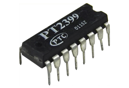
I come from a family of car nuts and this is about as close as I get to all of that grease monkey stuff. I had some PT2399 chips in my junk box, figured it was time to dust 'em off and build something.


Update 10-25-20: Why ever make one when you can make 3? Siff units add voltage control of time. Finished-all of them work--nasa, we have echo.


These 3 modules are based on the extremely popular PT2399 audio Delay IC, which as I understand it was originally manufactured for the Karaoke market.

The chip is super inexpensive--I got 20 from Amazon recently for about $1 each USD. When do you see that sort of price for specialized audio IC's?

There are quite 2399 kits you can buy: MFOS, Befaco, and more. But audio kits built "stock", to me are like building a puzzle: great way to pass the time but what are you learning, really? 

So I started down the path of coming up with my own echo unit based on this chip. First, the usual web research: The defacto "how this chip really works" page is from Electrosmash, here. Somewhat crappy datasheet for PT2399 is here, and diyaudiocircuits has a good page for PT2399, here. A good E-M page for 2399 is here. Trying to get longer delays out of it? I haven't tried it yet, but, go here.  

To get started, I found a github webpage (here), where the author, Joe Beuckman lays out a design very similar to the PT2399 datasheet's and posts it in Eagle format. And it's single sided. Great starting point; let's build it:

The PT2399 datasheet layout,  in Eagle format

Got the files from github, here. Opened it in Eagle, create the gerber and off it went to JLCPCB.  

Back!  Let's build: 

Here's the PCB:


The circuit needs 5V power and my Frac rig is +/15V, so I used the 15V-5V linear DC converter from a previous Arduino project, get that from my website here.


PCB front panel for test is left over from the noise! project.....

Bench testing, I found the input level to be a bit weak so I added a +6db buffer at input, simple non- inverting buffer circuit; get that on my website here. I used 2x 100K resistors for R1/R2 there, to get the 6db gain. Also, the 18K resistor R7 in the feedback loop seemed a bit high. I tried lower values (10K is better) but settled on a B25K pot wired in parallel with the feedback resistor, giving me  redundant control between the existing "feedback" pot and this new pot, which I called "loop". OK, between the two pots I can now get endless feedback. 

Then it was a matter of screwing it all together with 4x40 hardware. Easy.


Here's the read-to-test module, ready to go in the rack. Obviously this is a temporary front , but before I start adding VC, modulation, wet/dry and a whole bunch of other enhancements I have something to try out that gives me basic echo. And best of all, it sounds, to my ears anyway, surprisingly good--tops out at about 300ms per repeat, good for a $1USD audio chip. For 1000ms echos, or chorus, or flanging, or whatever else....you probably can't do any of that easily with the PT2399, but what the PT2399 does it does well. 

Temp front panel--very nice!

Original PT2399 echo w/ Mr. Label front panel. Finished! I experimented with "Send and Receive", buffering the feedback loop from PT2399's output to input; so you can plug effects into the effect. Works! Also brought out a buffered "wet only".  These mods and everything else are visible in the schematics for the skiff version, view PDFs for that here.

Next up: I already redesigned this basic PT2399 board to include the power and buffer and extra pot on a single PCB, allowing SKIFF if someone wants that, and will also fit behind a 1u Frac panel or about 6HP Euro. I repeated the buffered send and receive as well as bringing out "wet only". We're off the races on another fun organic audio project.

UPDATE 10-25-20: Skiff/REV2 units are done!  I made a PCB for the skiff front panel that had some mistakes, so I made a new PCB that fixed them. Besides needing kludge wires, Skiff #1 needed attenuation for VC in, which I added for round 2.  

10-31-20 DONE, no more echo please! for eagle files, PDFs etc, go to the web page here.

The two revisions of the jacks board for SKIFF; please enjoy the kludge wires for REV1 on the left.


The "main" board, for the PT2399 etc., worked first time although the TIME pot goes backwards, so CCW is fast delays vs. slow. Whatever, keeps me creative in the studio.


OK that's it for this time, until next time, don't breathe the P(o?)T fumes.

Tuesday, June 9, 2020

PAIA 2720-3B Filters: Gasboss and Unleaded

You can read part I of this post here....

Jumping back in: my first synthesizer was a PAIA, and this time, let's finish up a PAIA inspired filter from E-M guru Gasboss775; it's his take on a the classic PAIA bandpass 2720-3B filter from a bygone era.

I add details about building a 2720-3B "stock" clone as well.


You can read more about the Gasboss design on the E-M forum here. Again part I of this post is here. You might want to skim it.

A sound demo for the filters is  here, Go to my website (here) to can get schems, Gerbers, etc. etc. for the two filters discussed in this post.

Build notes: From the last post the Gasboss version was a single PCB, but why make things easy?

For the Gasboss module I added a "jacks board" to make this into a SKIFF setup and used PCB material (post here) and "Mr. Label" (here) to create the one-off front panel you see above.

Sandwich it all together with 100 mil headers and 4x40 hardware.

Worked--the Q pot turns the wrong way (so fully CCW is full Q), but, anyway, that will do:


I also added more input buffering and "BOWAL" (Bowal? ??? Post for Bowal is here) capabilities to the "jacks" PCB as well....bias offsets seem to help these filters deal with different CV sources so that's in.


My PAIA/Gasboss filter jacks board uses tall trimmers and here I learned something that should have been obvious: you can't hold a skiff front panel in place without 9mm threaded pots at the top or some damn thing to screw the front panel to. So, the front panel was wiggling all over. I ended up epoxying screws at the top so the front panel didn't move around; kludgey but it worked:


Son of a 2720-3B!! Just for S-n-G's, as long as I was fabbing Gasboss' filter, I figured why not send out a gerber at the same time that is a direct lift from the original PAIA schema, but modified very slightly for +/- 15V (the original required +18V and GND).

Why=whynot?

Orig 2720 schem--it's all over the Internet so I assume it's OK here?


Poof! Done, board is back, took about an hour to build?

That was easy, the original PAIA circuit is super simple and I think I successfully guessed what values are needed for the lower voltage rail by 3V.  Sounds ok and no smoke! I buffered the outputs, giving the world one goes outta at +6DB and one at +12db, because you KNOW you're going to need to crank up the output.

The 0db output isn't op amp buffered. Wasn't on the original. I guess 741s were expensive back then?


For the "stock" 2720 front panel I used Lazertran (how-to post here).  Decal graphics came out a bit crappy so I might redo it.

Some build photos--sorry.

2720-B clone, but +/- 15V.  I added buffers, otherwise no need for V--.


Used a 5x jack sub-board and 2x buffer non inverting buffer boards--one of two shown here.


Using the Gasboss filter and 2720-3B clone: For normal bandpass filtering uses, the 2720 is, well, subtle?  But! Right off--it's super easy to get either of these filters to distort. So you'll just crank up the input signal and pin that puppy right?  Nope. I noticed for both filters the band pass frequency sweep is less noticeable if you overload the filter at input. I don't know why--I need to think about that. To get the distortion and wah-wah action simultaneously, best to crank up the resonance--as you would with an MS20 filter.

I found myself attenuating the signal going into the filter and then cranking it back up at output. It got noisy and in some cases I got a 60 cycle hum when I really pushed up the output gain. But that's actually kinda cool--I don't have anything else in my rack that does that. If I need 60 cycle hum for some specific sound design need, well, now I know how to get it.

Another interesting use case is to put audio signals into the CV input. You get odd amplitude modulation effects doing that. I remember the 2700 PAIA had different jacks for audio and control (banana and 3.5" I think), so when we were youngsters we never thought about patching audio signals to control inputs; and it didn't dawn on us that we could make patch cables with different connectors on each end.

I remember doing a lot of wind/drum sounds with the PAIA 2700 back in the day and my old PAIA 2720 bandpass module was a big part of that. The 2720's are really good filters for processing pink noise. The Taiko sounds you hear in the sound clip demo (again--here) was created by using an aconitum noise circuit with the 2720 bandpass in series and the Gabbar EG--that was it. That got put into a BitBox 1010 and captured with Expert Sleeper modules back into Ableton.

Yeh, it's a pretty crappy sound demo--you can hear the filters at work but it's not my best compositional moment.  Oh well.

All the other sounds you hear in the demo utilized the filter primarily as a distortion unit, giving me grunge and grit which changed timbre as the filter swept. That's what the 2720 repop is best for as far as I can tell--for a VCF that only goes wah-wah you have a lot better choices.

On the demo everything you hear touches the 2720's somehow, the exception is the Roland D50-ish "big lead pad"--that didn't utilize this filter, sorry, the 2720-3B isn't right for everything.

I was a bit perplexed by the fact that these two filters never fully remove all input source sound, as you can with say a 24db/oct lowpass VCF. But then I found the other BP filters in my studio, including expensive fancy ones: they didn't either. Didn't know that about my bandpass filters.

Another thing to check out--use audio signals into these filters' CV inputs, in fact, try that with any VC filter. here, sticking audio or AM signals into the CV inputs, you get some really wild and strange distortion. Hours of fun.

Finished the PIE-Ah? So will the 2720 get a lot of use in my rack?  I don't know.  I kinda doubt it really. It's not a good filter for everything--it's not a good filter for a lot of things--but maybe no filter is. It does add another vehicle for me to get at distortion but I also have good DAW plugins for that (wait--DAW Plugins?) and get more precise control of the crunch.  That said, the 2720 has its own sort of distortion.

Nevertheless it was fun building these modules and remembering the good old PAIA days, when we wanted to sound like Rick Wakeman and didn't/couldn't; where the PAIA VCOs never were even close to being in tune, and DIY protogeek toys in our Central-Valley-Ranch-Home-Basement were the boss. Aloha!

JTAG to SWD Converter

Readers: If you'd like to build the project featured in today's post, please go to PCBWAY's Community pages--gerber file, KiCAD ...