If you want to skip what's below and just hear what the module sounds like finished, that's here.
Also: Part one of this post is here. You are going to want to at least skim the first post or the rest of this one may not make much sense....
Getting to it: after a PCB swap with Reverselandfill's Martijn Verhallen he was nice enough to send me the eagle schematic for his analog noise mixer so I could understand how it works.
His "Aconitum" noise board is designed something like this (it's more complicated, but this is the basic idea):
 |
| Simplified block diagram of reverselandfill's Aconitum noise board |
An NPN "avalanche" transistor gets sent through a couple of extremely musical passive variable filters, then mixed with two inverting op amp stages in series. There are accommodations for jacks and pots on the PCB, making it a good fit for your Eurorack modular synth.
NB: Martijn must have worked really hard on this design...."box stock" it's a really good sounding board. The filters yield extremely useful timbres for things like rain, wind, surf, everything between, all the way to frying bacon and back.
But "in spite of good tone, I can't leave anything alone?" For extra headaches I stuck C1406HA attenuator SIPS in series and added a 4th input for external sounds like this:
 |
See more about C1406HA's from my last post about this project; in general the C1406 is an easy to implement voltage controlled dual attenuator SIP IC--in goes audio and CV; out comes audio levels based on CV--the more CV, the more attenuation. It's like a VCA that can only cut amplitude, not boost it.
One of the challenges for this build (other than some bonehead mistakes on my PCB--more about that in a bit) is that I use FrakRac and Martijn, like many more sane DIYers, uses the much more popular Eurorack format. So I had to piggy back my board below his to make this fit in my rack:
 |
| Thank goodness for 4/40 hardware? |
Once I got all that bolted together, I separated out the boards and panel and got to work with stuffing and wiring them.
 |
| Aconitum board is on the right; my custom panel and quad attenuator PCB on the left. |

Good news here: Martijn's board is flawless--no mistakes--nevertheless, he emailed me a few times to say he is improving it....cool! Martijn also PM'd me to say that he owes the legendary Thomas Henry and Ken Stone for design ideas for the Aconitum board.....if you get your hands on this board, for me it worked with +/- 15V without any mods, even though it's designed for +/- 12V.
Next I wired up my REV1 C1406HA quad attenuator PCB fresh off the DHL boat; and this is where my problems began:
 |
| The original schematic--anyone interested, I will post it in Eagle and PDF.... |
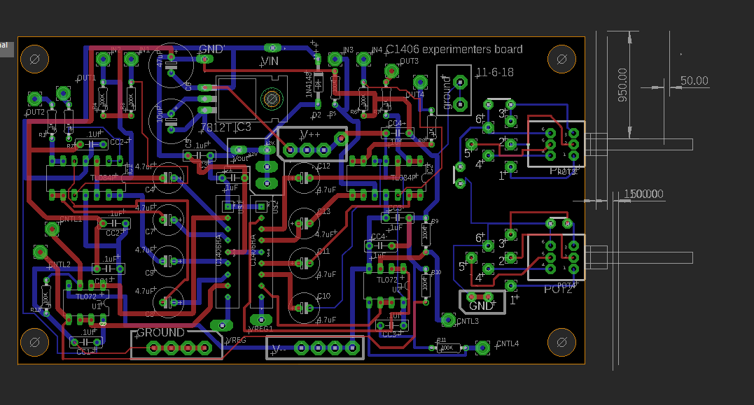 |
| C1406board Rev1: a Plague of Locusts. Here I've already fixed the power silkscreen issue..... |
I rushed this design and fab and made some really stupid mistakes:
- the V++ and Ground silkscreens on REV1 of the board are drawn backwards. Really? Um, yep! Traces are OK but the silkscreen says to wire the power supply's V++ to Ground and visa versa. Doh!! Nothing blew up, but my board obviously didn't work at all until that was straightened out. It took me an evening of head scratching to figure the errors of my ways....it was such a dumb mistake it took me a while to realize, hey, everything is backwards!
- I forgot to put 100K resistors at the "output side" of the 1406 output decoupling caps. Since these caps are tied to a TL084 (super high impedance inputs right?) there was nowhere for the current to go so the decoupling basically didn't work at all, and I still had a DC offset at output. That's something my first tech boss always told me: always give current somewhere to go! You'd think after 30 years I'd get this right, but, nope. OK kludged some 100K's on the bottom of the board....now the cap coupling works--fixed.
- the C1406HA can't really support 10V P/P. So its input needs to be gained down, while its output needs to be gained up. That remained unfixed; I just have to watch pegging the C1406, but I guess sometimes the pegging doesn't sound that bad (but often it does). I'll put 6db gain at output I think on the next run. See R21 circled below--this is the standard 6db gain op amp configuration, that's the idea.
Some schematic detail about the resistor issue:
 |
| You need resistors R13, R14, R15, R16 to have upstream capacitor decoupling work! |
 |
| ...but my original design was what you see circled in blue, non inverting buffers....which didn't work. |
OK I kludged/fixed all those mistakes. Yes it's a pain to have to kludge prototype boards, but perf boarding all this would have been way more work.....
For those who want to share the pain: I have a revised board ready to be fabbed--as usual, any takers on trying the improved one out? no takers? OK I will get to checking REV2 one of these days, but the REV1 board works, anyway, after I have fixed all the DUMB ASS MISTAKES. I might make a smaller stereo version as well....
Moving on:


I wired the two boards together--a lot of wiring, but nothing too difficult.
 |
| All done but no panel decal; ready for testing |
The good news is after all of this I got (I think) some really good sounds out of this board. Take a listen on Soundcloud here.
Details about the demo:
As usual the demo was made fast, fast, fast. If I can do this in a few minutes, you should be able to better in say 15 minutes right?
00:00 to 00:28: Surf part I. Each noise source in Aconitum went though an its internal passive filter then through the Aconitum's built in mixer. The wave crashes were produced by a slow random gate generator which was fed into an ADSR, which was then used to produce CV; that CV attenuated noise ("Tone1") using a C1406HA CV controlled attenuator. Tone1 was set to a very bassy, boomy filter sound. NOTE: I cheated a bit on this one: a tiny bit of phase shifting, reverb and bandpass filtering was used in series with the output to make it the aconitum sound a bit more "other world" but you can get good surf sounds stock right out of box (listen to the last cut of this demo?).
00:30 to 00:45: LFOs feeding the 1406 attenuator. Each of the 3 Aconitum noise sources had a different LFO input attenuating noise. The output of the Aconitum's mixer section went into a vactrol bandpass filter, getting rid of very high and very low frequencies so your speakers and ears aren't destroyed. With some screwing around I probably could have gotten close to the Apocalypse Now "Helicopter Whup sound", maybe for another day.
00:45 to 01:00 same thing as 30 to 45, but different LFO settings. The "sprinkler" sounds were created by using a CV controlled LFO.
1:05 to 1:30: I put a drum machine snare and kick outs into envelope followers and used that to trigger ADSRs which fed the C1406HA attenuators. The kick and snare noise sounds you hear are substitutes for a 707 kick and snare. The hat sound was fed into the "external" attenuator channel and passed through to the aconitum's mixer.
1:35 to 1:45: A byproduct of setting up the gun range sound (which comes next). Fast Random gates hitting the noise attenuators and also throwing the sound into a stereo panner that was very quickly panning between L and R channels. Produces a frying bacon sort of sound.
1:45 to 2:15: The gun range. Each output of the aconitum (noise, tone1, tone2) was fed into 3 VCF's and 3 VCA's. The VCA's were modulated by ADSRs, each of which was driven by its own random gate. this went into an external mixer and into my recorder.
2:15 to 2:40: Same as 00:00 sound but I changed parameters to make it sound more like traditional surf.
BACK TO THE BUILD: Final step after testing and seeing what it can do was to decal it.

Ok that's it for now.....Overall this modified board swap module was a lot of work but I had a lot of fun building it, and it's already become a really useful addition to my DIY modular synth. I think it sounds really good!
Not sure what I will work on next but the MCU world is calling me again. My girlfriend (who btw is a mental health professional) says I have become too obsessed with DIY, and I need to take a break, so I am almost done w/ week one of a two week lull. Did I breathe too many fumes? Maybe! And always remember: "Sanity is relative".


No comments:
Post a Comment