Bias Offset With Adjustable Level, AKA "B.O.W.A.L."--EZ Op Amp Circuit that worked the first time!

Almost nothing makes me happier then laying out a PCB, getting it fab'd, stuffing it with parts, mounting it to a metal panel, racking it, and having it (wait?  wait?) work the first time !!!

NO MISTAKES!! No kludges, no cutting traces, no gnashing of teeth. Yeah!!!

What is up: While I had the Zener Distortion Units on the bench I found this: if I offset the audio signal(s) feeding it by a few hundred millivolts or more the zener unit's sound at output changed quite a bit.

I also found that in my growing DIY modular synthesizer I had very few ways, if any, to create this said offset.

Let's get building! The usual: researched, opened up Eagle, designed, checked, sent it off to JLCPCB for quick fab.....

While we're waiting for the PCBs to come back to the US now what?

As Frank Zappa used to say "let's examine this phenomena!"

Q: What do I mean by offset?  

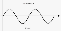
Say you have a sine wave, and it's centered on 0V DC (ground).

It will look like this on a scope, or, if you hunt around Google and copy illustrations to your blog:


The bias offset will "elevate" the sine wave to something more like this; and it can go either way; apply a negative DC offset and the sine wave is dragged below zero, but here it is above:


At first glance, this doesn't seem like a big deal, but in terms of modular synth, it can be useful.  Put your waveforms through the bias offset device, change its bias level relative to ground, and put it through a ring modular.  Ha! Sounds different!

Q: Still not convinced, but anyway, how to design this? 

There are lots of ways; but like most every other analog designer out there, I like using op amps.

On my website I already had a non-inverting design for this, but it requires small value offset trimmers or pots, say 1K or 5K, which might draw too much current if you add say 8-12 of them to a design.  I don't use battery power but if I did you probably don't want to do this!


I don't spend a ton of time worrying about power efficiency but still, it's good to do things right. OK, lets put a bigger value trimmer in for the 5K above....let's make this trimmer 100K to keep our power supply completely happy, and the resistors in the op amp's negative feedback network are also 100K.  But wait, now, the gain doesn't come out right--the offset resistors screw up the output:

Audio goes to +; this circuit draws relatively little current--but-your gain will not be what you expect!

What I figure: an inverting solution ends up working better when the power supply draw is critical. .

Enter B.O.W.A.L....a simple quad inverting then re-inverting op amp PCB with 2x quad op amps.

You can see details about PCB layout on my website but basically the circuit board looks like this:


While a single gain stage (repeated 4x) looks like this:

It's important to remember that offset voltage to pin 12 is inverted--so V- makes the bias offset at pin 14 higher....


For my own B.O.W.A.L. I added a brain dead AC coupler to undo whatever the offset circuit does, creating a "star belly off machine", entirely wired to the front panel.  The Offset pot above can be a trimmer for fixed applications, or a pot on the panel so you can adjust the bias on the fly.

Aside: a really good guide for setting op amp bias offsets can be found here: MIT's "how to bias an op amp".  (Note that my undergrad application to MIT in 1980 got the big goose egg. I wonder why?)

So anyway this PCB got back from China and I populated it, selected an unused a front panel, got some pots from Small Bear going etc:


Designed up a front panel for Lazertran using Adobe Illustrator:


As I said! worked first time. Yeh!


BEWARE: if you amplify and/or offset your incoming signal too much, your op amp will squash the dickens off some or all of your incoming signal, turning it into an ugly square wave. To my ears, this isn't good sounding distortion, this is really bad sounding distortion. At best an op amp can gain something up to slightly above its V++ and V-- rails, and usually less. So keep your amount of BOWAL output flushable....

And: if you are really concerned about input impedance you may want to put yet another buffer in front of your B.O.W.A.L. or change BOWALs R values.  The incoming sound will travel through all the feedback resistors from input to output, which might yield a different input impedance than you want.

Update!  The +/- 15V DC bias settings weren't working for me sound-wise--it was too easy to distort incoming signals, which sounded terrible, so I did this easy mod to the 4 bias pots (in my build, these are inner pots of dual concentrics from Small Bear:)

"To PCB" means wiring to the center tap of the bias trimpots on the circuit board.  The down arrow is -15V


I used different resistor values between V++, the pot and V-- to allow for flexible settings

UPDATE to the update: After messing with this design a bit more, I realized the circuit would be more musical if I could control voltages to determine the bias offsets. And that's easy, buffer an incoming CV signal and feed it to each of the op amps' non-inverting inputs. I thought about modifying B.O.W.A.L. to do this, but the front panel was already done and labeled.  Instead, I  created a 2 channel variation of this same PCB that has CV to DC bias offset: "Small B.o.w.a.l".

UPDATE 9-27-21: another interesting use for BOWAL can be seen in the Dual Wasp Mixer from CGS (here). Look at the circuit fragment in the upper left corner. "CV-" in this design not only sets CV bias offset but provides inverted control voltage to the filter's cutoff frequency. This is because the CV mixer inverts the CV, but the non inverting input of the op amp used to mix CV inverts the inverted signal (I had to think about that one for a bit). You can add this to your BOWAL by putting a 100K resistor between the offset Pot and the + op amp's input....then putting a 100K resistor in series with the incoming additional CV and tying that to the non inverting op amp input as well. You'll end up with a signal that both sets bias offset and presents a cool inverted CV input into your design.

OK that's it.  Remain biased at all times! Until next time, go MITEs and don't breathe the fumes!


Zener Synth Distortion: alive and kicking (with sound file and scope photos)

Hello Again.  This time closing out the "Zener Synth Distortion" Project.

You can read Part I, how I stumbled upon this circuit, here.

2x zener prototypes, each slightly different builds, are up and running,  panels Lazertran'd, ready to go.


This is a super simple build, almost no parts!


How does it sound?  you be the judge! I have uploaded a demo sound file on Soundcloud.

I tried to give the most objective before/after demo of the 2 modules I could. No reverb, no filters, no echo etc. boring right?

Here is how I patched my fully DIY home-grown-works-almost-all-the-time modular synthesizer to get the demo sound going:

On the demo the first few sounds are from the "Zener" design:


"Zener" provides in your face, loud, crunchy distortion and greatly emphasizes beat frequencies.  maybe a bit much?

The rest of the demo (the last 3:30 or so worth) is "Son of Zener", a lot more subtle.


Shorts anyone? On "ElectroMusic" forum there was discussion about buffering the inputs (so 2 input signals don't go through both inward facing zeners and short one another).  Ach Tung!  I added a single unity gain buffer to one side of each design.  Update: After a bit more discussion with Phobos from the site, it makes sense to buffer the Son of Zener input as well, since the transformer only supplies about 45-50 ohms of resistance.

Another thing that came up on the forum: what do these distortion doodads look like on a scope?  My Siglent save to USB stick doesn't work (Firmware issue?  Damn!  Says save, then nothing on the stick!) so excuse the crappy photos, but here it is:

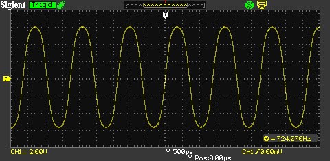
Source waveforms look like this of course:


Mixed, through ZENER they look "square waved" as you might expect (note the DC offset--you may want to get rid of that if you build this circuit--cap coupling should help, but me? I fix it soon....)


But other times you get messed up sine waye craziness......


In case there was any doubt, it's not true ring modulation; again I think the circuits beef up any beat frequencies, sometimes they jettison the fundamentals entirely, so you get oddness (hear it in the demo?)....you end up with something that reminds me, sometimes? a bit?? of ring modulation.  And I can't figure out why the transformers are necessary, from my limited knowledge of inductors, they shouldn't be, but trying these designs the bench without them yielded less "effect" for things like the pseudo R-M sweeps.  Sorry, i  can't say why....

OK that's it, time to move on. I can fab a PCB of this if anyone is interested; I can't charge you for 'em, sell em on etsy or whatever, due to the deal I have with my current employers, but I can send a "freebee" out to whoever is interested (help me w/ postage?  Whatever....)  If there is any interest I'll get that going. Until then enjoy some Ziener for your wiener.....This is a super easy circuit and I'm sure can be improved.  Different value Zeners?  More buffering?  Figure out if the transformers are needed or if I was listening to too much 80's pop while I was prototyping? How about an AC offset in front of each input (which changes the sound).  Please let me know whatever you come up with. Have fun!

Thomas Henry 13700 based VCO: All hail the mighty Henry!


How much have I learned from Thomas Henry's books?  Well it's all relative I guess, but for me,  a lot!  I went from zero knowledge about OTA's to well, some knowledge. Two of his books are both recommended if you want to learn how OTA synth circuits work: "Making music with the 3080" and "An Analog Synthesizer for the 21st century".

Each book features schematics for different VCO's.  The former, 3080 based; the latter 13700.


If you've studied audio DIY for synths you've probably run into these IC's before; in goes (low) voltage; out comes current, and best of all, you can control the output current in a linear fashion (hopefully) with an independent "gain" current at a dedicated input.

But it's not quite that easy:
  • The gain current input lives a diode drop above V--.  So to make this go, you often have to use PNP Transistors which seems to me oddly counter-intuitive. Hello?.....OK....
  • If you put too much current into the gain pin (2mA I think?  1mA? don't remember but it ain't much) you blow the crap out of the OTA chip.  You don't get a buzz, a hum, smoke or whatever, it just dies and never works again--fast, like in milliseconds. OTAs are fragile!!
  • And these damn things can be expensive to replace!
  • The input gain control to output current is a linear relationship, but only for a narrow band. If you outside this band, it's distortion city. No, not 6v6 cool sounding distortion--really crappy ugly sounding distortion.
  • The voltage at input needs to remain small, like 30mV?  Don't remember that either, but it's not much.
There is really good information about all of this, that a non-EE, nearly deaf, never-made-it-as-a-rock -star guy like me can follow, in the 3080 book.

The 3080 and 13700 OTA ICs are obsolete you say?  Ha! you can still get 13700 clones from CoolAudio and I still see 3080s come up for sale every now and then on Ebay, Mouser, surplus places and the like.

I've now built 3 TH OTA VCOs as I write this.

UPDATE!  Sound clip added. I find myself using the THVCO's a lot for FM type sounds. Because of their pure waveforms and large frequency range, they are very good for that.  Sound demo is here.

About the VCO's: The designs aren't quite as simple as the ASM VCO but yield really good looking triangle and sine as well as pulse and ramp, with good stability, a wide frequency range (putt-putt LFO to way too high for me to hear), and good V per octave performance over about 8 octaves. TH probably put a ton of work into these designs and he deserves our gratitude.

Nice to have another 3 VCO's in my rack.

3x THVCOs.  Not fully labeled yet, but they all work.

 I still need to do the LazerTran phony silk screen to the left two units.

OK, Done.....


For all three: No mods really, except I had to change op amp gain at the output of the sine waves to about 4:1.  What is in TH's books come in at about 1V P/P sine for everything I built. That's too easy. Easy fix: change out a resistor value in the output buffer for sine.

BTW the waves look really good on these VCO's!


Details on the fab: There are lots of ways to build your own THVCO, including buying PCBs from  guys online (licensed sometimes, sometimes not?) who will gladly sell you THVCO inspired PCB's.

For me, I always fab my own boards (easier to mod, for one thing), but for this, a single printed circuit board using all through hole would have been huge--a lot of parts--and my Fracrak case is not that big, so I created a "motherboard" and then used 4/40 hardware to screw daughter boards (3 of them: CV volt/octave to log; OTA VCO core; waveform generation from triangle) to each one.

the boards lying on the bench are the motherboards. 
Dual concentric pots are huge spacesavers!! I get 'em from Small Bear....go SB!

As always front panels are from PCBWAY (I ordered "alubase" PCBs); dual concentric pots from Small Bear; PCB's from JLCPCB. 


Holy smokes the 13700 VCOs were a ton of fab work. I need to get into SMTs I guess, and not do so much wiring, but I often modify my designs after they are in the rack and nothing beats through hole components and 22 gauge hook up wire to facilitate that. It took me 2 weekday evenings and 2 solid weekend days to get them stuffed, assembled, wired, debugged, calibrated, and in my rack.  Another 1/2 day to create and apply the front panel decal.


Wrap it up already! I can't in good conscience post TH's schemos anywhere, so please buy his books, but for build notes (this is mostly for me I guess....) I scanned everything I did and put it on my website here. Eagle files for the motherboard and some other goodies are linked in the same part of the page. Note there are 3 mistakes in the 13700 work, all of which are easy to fix, and the fixes are in the PDF docs. I'll go over the 3080, which is a pretty different build, and destined to be used for waveform experiments, another time. At least everything fits in my rack!

Until next time, don't breathe the fumes!
Discovered by accident: Low parts count waveshaper/modulator/distortion circuits!

At the bench trying to learn more about inductors--something I've not worked with a lot with before--so bought a few Neutrik NTE1s from Amazon.

It's a 1:1 transformer (making the math easier I figure) and has decent audio specs.  And it's cheap--about $14USD each, for decent audio performance; good for experimenting.

What can we do with this little gadget?


Benchtime! my goal one day is to come up with something cool like the Moog 914 (yeh right, I have a long way to go).  breadboarding up some transformer/cap widgets, got bored, some inductor/transformer/RC/op amp widgets, got bored again, so breadboarded some transformer/zener widgets,  when all of a sudden I heard what sounded like a balanced modulator coming from the my bench's audio monitor.

hello?

I looked over my work and realized (after a bit) an op amp I was using as an output buffer was oscillating (unintentionally) and I had wired things backwards, confusing the breadboard inputs with its outputs!!

So instead of 1 in and 2 outs, I had created 2 ins and one out.

I stopped everything and drew out what I had done since i liked the way this accident sounded. it's this:

Almost forgot, output resistor is 1K!

How does it sound?  Well, "It depends".  For low frequencies (say less than 2K) maybe like a cheap guitar distortion pedal.  For higher frequencies, especially when you sweep different sine or tri waves from say 8K down to < 500hz through the 2 inputs, more like a classic synth balanced modulator.  From there I can get all different sounds--fat sounds, thin sounds, odd sounds.  Waveforms beating with each other, with beat frequency changing as I lowered the input frequencies.  Odd.  Not everything sounds good, but some things do.

What waveform goes into in 1 and in 2 makes a huge difference, and what amplitude/what dc offset matters as well.  Sometimes if I didn't like the sound at output I'd switch what was plugged into inputs 1 and 2 with one another, and I'd have a completely different thing going on.

The son of zener above creates about a -3db drop in amplitude, input to output, so I added the x2 gain op amp above....up to 9 parts!  Damn! but if you're serious about making this passive only (no batteries! No power supply!), you probably could do without it.

Figuring I might have stumbled on something? I got out another breadboard and came up with this 8 part variation:

Since I like this one's sound better this is "zener"  other is "son of zener"

From design #2 I got weird beat frequency stuff, balanced modulator stuff, all sorts of things.  For this one the 4x op amp gain stage is necessary since the transformer (? something?) introduces a pretty big amplitude hit.

Anyway, I strip boarded it, and used some simple op amp PCBs I had created for other projects.

Here are the obligatory bench photos--the zener prototypes literally took minutes to build.  If anyone wants to screw around, or knows of other designs like this (I don't, other than zener based guitar stomp boxes--which I guess these are? But zener and son of zener seem to require the transformers to get the odd BM sounds? I couldn't reproduce the exact same timbres with op amps) let me know.


Still to do: make some demo wav files, and panelize this.  UPDATE: Done!  Go here!  Until then, don't breathe the fumes!

Tape Deck Mult Panel--An Easy One (Two)


Nothing like finished panels....


I guess I like the Tascam SS-R220 stereo solid state recorder....I own three of these....
What is good about these?


  • Good bang for the buck
  • Decent A/D D/A without paying a fortune
  • Digital IO so you can use better D/A if you want (I use a UA 2192 and one of these for mastering--always liked the way the 2192 AD-DA sounded).
  • The SS-R200 RCA inputs accepts synth 5V P/P signals without a lot of fuss
  • Good, easy to use front panel UI
  • Good manual
  • Works on SD cards, which are cheaper (and taste better) than a Big Mac
  • Remote control with a long cord (hey!)


In other words, someone at Tascam did good work on this one.


So what does this have to do with DIY?  I want to do sound on sound, 2 of these in one rack, so I figure I'd build a couple of quick mult-panels to accommodate, with some normals etc.

After sleeping on it, bingo, I know how I want to do this.

Hand drawn wiring setup (rear view) looks like this:


I use 3.5mm "normalled" TS jacks for my DIY work--I had to choose something, and always thought on the ARP2600 this was a good combination of size, convenience, and ease of using normals.

I already had about 6 unpopulated alubase panels I got from PCBWAY.

From here building 2 of these was easy work.  After mounting jacks and soldering up the mults and normals, I cut the one end off a couple of junk RCA stereo cables I had and used the cable and remaining males.

Here it is in my Fracrak:


Still need to label the panel, using Lazertran, but I am finished with the artwork already:

One of those things that's fun and easy.  


OK off to put some guitar parts through a Balanced modulator.  I'll have sound samples soon.  Really!


Getting started with AudioDIY and the Atmel ATTINY85: What to do with these tiny things?

UPDATE!: I have written two additional posts (so far) about ATTINY:

Pros and cons and debugging here.
Arduino Interrupts using ATTINY85 here.

OK back to the original post:

Hello Again! I can't help but be seduced by an Arduino that, from about a foot away, looks like an op amp. And costs only a bit more!!!

I'm talking about the ATTINY, which in its "85" form looks like this:


Can we really pack an Arduino punch into an 8 PIN chip?

Time to find out!

I bought a few of the ATTINY85's ($2-3 for DIP, good for prototyping; under a dollar US for surface mount) and a Sparkfun programmer for about $15 from Amazon:
From my reading, programming ATTINY using the Sparkfun is pretty straightforward--I figured I'd have the LED blink app up and running in 10 minutes?

But it didn't work!  10 minutes became a couple of hours....

Hello?

I have 2 computers I use for Arduino programming on my bench and the Sparkfun programmer didn't work on either: an older MacBookPro running OS-X Mountain Lion and a Lenovo T430 running CentOS 7.  I have used both many times for programming Nanos such as the one used for the SynthDMV.

After following the Sparkfun instructions (which are very clearly written--good work Sparkfun) several times, no go; it's like the system couldn't find the ATTINY85 chip I had put into the programmer.

Driver issues?

Many documents on the web say for Linux and Mac you don't need drivers for this Sparkfun Programmer--only for Windows and thankfully I don't do Windows in my electronics lab....too much Windows at work, don't need that here as well!

But still it felt like a driver issue.


Lots of head scratching....odd that I saw this "hide the ATTINY" issue for both laptops (different OS's right?  different hardware)?

To make a long story short, I found other poor sorry fellow dumb SOB's who had the same problem, and one of them suggested "try a different USB cable".  Well, I wasn't using a USB cable at all; I was just plugging the programmer into an open USB port of either laptop.  Seemed at best like a long shot but after 2 hours of messing around with this I was ready to try anything.

I dug around in my USB cable crapola box and found a M/F USB 2.0 extender--a standard M/M USB cable wouldn't work--I plugged the Male into the Mac, the Sparkfun programmer into the female side, and of course after that the programmer worked!

Now that makes no sense at all....i could see the programmer being unhappy with the USB port on one laptop, but not two, and running different OS's at that--and it didn't work on any USB port anywhere, but with the USB extender cable it worked everywhere.  Makes no sense!!! 

I posted this on an Arduino Forum and got zerohttp://forum.arduino.cc/index.php?topic=388043.0 responses, so maybe of the 7.7 billion people on the planet I'm the only one to have ever have had this problem?  Whatever.

UPDATE!! FIGURED It OUT! It had nothing to do with cabling, drivers, or anything else. both the mac and linux machines are linux based and both weren't giving the programmer permission to program. I still don't know why the system worked after I changed out the cable, I must have done something else (run arduino IDE as root?) total mystery until I found this. Here is how to fix this issue:

  • From your linux box, open terminal 

  • issue the command 

lsusb

  • note in the list which one is TINYUSBISP: for me it is this: 

Bus 003 Device 030: ID 1781:0c9f Multiple Vendors USBtiny

  • now issue this sudo command where the last 2 numbers match bus and device numbers spat out by the lsusb program. 

[clamm@localhost ~]$ sudo chmod 666 /dev/bus/usb/003/030


fixed!

Onward!! Anyway: now that the BLINK proof of concept is working--a few things to think about:


  • There is no "official" I2C library for the ATTINY.  I see folks using this "BroHogan" i2c library; I have yet to test it.  So my favorite I2C goodies like the MCP4725 D/A are not supported using the more familiar wire.h library, but that's probably OK.
  • SPI is the same deal--but you can apparently use this guy's software to do SPI with this chip.
  • There is a LED on the programmer--D0--that does help a bit I guess.
  • There is no built in serial I/O in this system, which makes debugging harder.
  • You have to supply your own 5V power supply--to power the chip as well as any peripherals--there is no 5V regulator on board, as there is on the nano.
  • Tinkercad Circuits, which I use all the time to bang out virtual Arduino code to then use in the real world, supports ATTINY. And from messing around with it so far: at least some of the slightly more arcane features, like Pin Change Interrupts, appear to be supported.  yeh!!!
  • The Programmer you see above has breakouts for the pins on the ATTINY--so you aren't schlepping the chip in and out all the time--very useful.


OK time to put this on the bench:


Yes, blink works, analog in works, basic interrupts work, and so on.

After an afternoon of messing around, two designs came to mind that might be good candidates for projects based on this chip:


CMOS 4051 based CV selector based on incoming control voltage:


The CV is read by an analog pin (need to condition the CV to be 0V < x <5V, but that's not too hard) and then used to switch between CV fed to 4 or 5 of the 4051's inputs.  Any audio would have to exist between 0 < x <5V as well, but if you can massage the audio to that range, that should work as well.  That's all simple op amp stuff right?


Update!  I have this 4051 switcher working in a simulator, read about that here--the 4051 business is at the very end of the post.

Or, a low parts count (I think) trapazoid generator:

Hope I am not using too many IO pins here!

Overall though I keep going back to this nagging thought--why not just pay an extra $4 or whatever and use a nano clone? You get more pins, more options, serial for debug, etc. Of course the Nano is bigger, but not too big for projects that involve 1u Fracraks which is the smallest thing for which I'd probably use Arduino.

So I am left wondering what if anything AudioDIWHY I will use ATTINY for? Guess time will tell....

BTW I think these guys are burning audio stuff onto ATTINYs and selling them as finished audio DIY chips.  So the tenement version of a VLSI chip making operation. Just a guess? Makes sense--and if that's what they are doing: clever.

Regardless it's cool that fellow hackers have made an Arduino IDE-ready chip that's this small.

OK that's it.....Until next time....as always, don't breathe the fumes.