Thursday, May 24, 2018

EAGLE PCB--Getting Rid of NAMES for Board Components

Full disclosure: 

I use Autodesk's Eagle for PCB layout.

So this blog entry will only be useful to you if you use Eagle vs. other means of laying out PCB's.

It will also only be useful if you use Windows; I suspect the Linux and Mac versions of Eagle are set up differently in terms of where the files go.

And-- I am using Version 9.0.1 of Eagle as I write this; Autodesk changes Eagkle all the time, so I can't guarantee this will help you if you're reading it 3 years from the date of this post.

If you don't know Eagle pretty well you want to skip this blog entry, it won't mean squat to you. But if you use Eagle all the time, as I do, it might be useful.  OK without a lot more blah blah:

Here is the issue.  

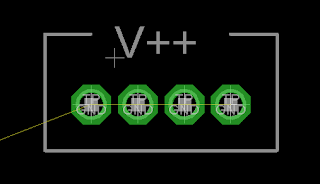
When I am designing a board layout, a series of Pads might look like this:


When how I want it to look is this (note the absence of what Eagle calls "NAMES")


Pads without names is useful in some situations--I can now use text tool on the tNames layer to silkscreen a clear callout, in this case V++:


So how can you remove names?  You can't call a named part "" (so, no value) or you get an error when saving.

The only way I could figure out how to do this is change the actual part itself, getting rid of the >Name placeholder for each part I want to use on my board, and save it in a custom Eagle Library.

Fortunately it's not that hard to do.

Here are the steps:

  • Close Eagle if it's open.

Create your own library after making a copy:

  • The libraries that come with Eagle appear to be read only.  
  • You will have to copy an existing Eagle library to a new custom location you create.
  • In my case I added a new folder to Dropbox so I can use my custom libraries across different computers, but any folder you have to which you have modify privileges will do.
Next, open Eagle and go to their "control panel" which looks like this--it's the first screen you see when you open Eagle; you can't have any boards, schematics etc. open or this will never show up.


Tell Eagle where you are going to put your custom libraries. 

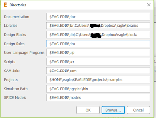
Go to Options >  directory, click in the Libraries field to add the new folder you created for custom libraries.

Click Browse > Open.

Navigate to your custom library location and click OK.

Eagle will now look not just to its default locations for libraries but to your new folder as well.


Copy a library into your new library repository so you can edit it.

Hint: Eagle provided libraries in Windows 10 and probably Windows 7 live here:

C:\Users\[your username]\AppData\Roaming\Eagle\lbr   

You knew that right? You may have to unhide hidden system files to find this content.

  • Use Windows search and look for a library like this one:

testpad*.lbr
  • Once you find it, copy the testpad*.lbr file to the new "personal" library folder you created above.  Yep, all you do to "import" a stock library is copy the file to a different location.

Edit the personal library.  

  • Close any boards, schematics, etc., you have; you must be back at the Eagle "Control Panel" (not to be confused with Windows control panel!) 

Now issue the command:

file > library > open

Open the personal library you just copied to your new folder.

Again, try as you might, as far as I can tell, users cannot edit libraries that were installed when you got Eagle going--only ones you copied somewhere else. Am I wrong about this?  Anyone?

Time to edit--I am now going to edit the testpad.lbr library, and specifically the group of parts called "TP":


Expand the lbr file as you see on the left of the screenshot above, then Right click where I have the Blue Hi-light, the TP set of devices....I do this because TP has the specific pad I want to modify

Once selected, right click, and from the pull down, left click Open In Library".

A new window opens--the library editor.
  • You will see a column on the right....select the individual part you want to edit by left clicking on it.
  • Then right click on the part that needs its name blitzed--in the screen shot below I have circled it in red:


When you right click, choose "Edit Package" from the drop down.

This takes you to the package editor, where you can get rid of the part's name--choose the garbage can icon, then left click on the + to delete the part's name:


You can also change the description by clicking on the description link and adding HTML for the part's description.  Maybe change description to "TEST PAD-no name"

After the name is gone, hit the save (floppy disc) icon.

To change more parts, go to Library > manage devices and start the process again by choosing the next part you need to alter.

Using the Library

You get a library of many pads with the Names already removed from my GitHub. These are libraries where the entire TP device collection--about 20 parts--all have their names removed....I use this any time I want to use Text on the tNames layer vs. part names.

To use these parts, fire up your schematic, and use add > library manager > browse and find and then select your custom library.  Pick the custom parts you want to use and drop them into your schematic.
For ones with the names blitzed in the manner above, the schemo will still show you a part name, but on the board it will be sans name.

UPDATE: I have used the "nonames" parts above several times now for different PCBs.  So far, all seems to work. In the meantime, if you have comments, questions, or find a mistake in this blog entry, please comment below so I can fix this thing.


Monday, May 21, 2018

One Cheap Arduino Nano Clone-o Plus one Cheap 1.8" TFT Display = An Entire Sunday!


Who can resist Amazon Prime Points?

Who can resist a cheap TFT display?  (I couldn't)

A million and one uses--as I develop my skills with Analog DIY and Digital hybrids I can justify all of this right?  (right???).

My goal this time: to design a simple DVM I can incorporate into audio gear. OF COURSE I can buy a DVM for like 25 cents that will probably work better.  And OF COURSE I already have  DVMs already. So why not stash one in my studio and use that.

(Answer: what fun would that be?)

Along the way, getting TFT displays going is an unfamiliar process for me, having never worked with a small display like this.....as well as understanding more about DACs, ADCs, and in general,  creating semi-precision applications--usually I just throw op amps at things and hope they work?

Anyway: these clones appealed due to their super low price ($6.50 US on a good day?), good online visibility and online .h libraries already written, like the Adafruit 7735 library

So just fire up an Arduino Nano clone, wire up the TFT, load in the Adafruit test sketch, and go?

Nope--Not that fast!

Here is the pix of my first Arduino clone….


I discovered the clones are.... "diff'rent".

To wit: some clone Arduinos don't use an FTDI USB chip you find in real Arduinos--the clono cuts corneros and uses cheaper USB chips.

So the drivers you have in your PC, used by the Arduino IDE to talk to a "real" Arduino chip, may not work with the clone board.

How this manifests: It's like you never hooked the Arduino up via USB at all--there is literally no USB port for the IDE to use to upload code to the board.

This is a first world problem.....

OK what to do: go to the Internet of course.

Turns out you can flip over the clone board and read the chipset used for USB, and google that to get the driver online?

But for my Nano clone, someone had scraped off the chip designation.  NICE!!!

From research online: this is the chip used to control USB on Clono-nanos but who scraped off the damn chip designation?

So I did what every tech does: I had to guess. Trial and error? I **hate** trial and error when fixing things!  From more reading: most clone Arduinos use CH340 USB chips.  The SOC layout of the USB chip looked like a CH340-CH341 so maybe that's what it is?  Just get the driver and go?

Driver is here  PLLUNNKKK!!!

(WARNING do not use this driver!  I took out the hyper link above!  It crashed my Mac!)

WTF???  I am using a Mac Sierra.  the chip's mfgr site says to use USB V1.3 for Mac. I downloaded that driver from the .cn site that will not be named and poof!  OS crashed.  mac unbootable. Yes, Elmo, the driver downloaded from the .cn vendor messed up an otherwise working Mac and made it unusable.  And maybe installed a keystroke reader and god only knows what else? VERY VERY NICE!

Forturnately I fix computers for a living so getting the Mac back wasn't that hard....the whole command + R thing.

Then a thorough anti-virus/anti malware pass. I  removed the butt driver and the Mac booted fine and appears to be secure again.

Back to square one--I still have the initial issue--how do I talk to the Arduino Clone?

Turns out--you need to get "the patched driver" for CH340/Mac OS sierra after removing the butt driver.

Time wasted: about an hour.  Arrg!

Now--with the right driver--now at least I can see Arduino no name-o Clone-o Nan-o and upload my code to it.  (OK no more o's)

Marvey. how do I wire the TFT?  How do I send proof of concept test code to it?

Trial and error pretty much? This time I felt it couldn't be avoided....

The TFT 1.8" device is a no-name unit with zero documentation. No links to the vendor's site. No vendor name silkscreened on the PCB I can use to track down  the pin-out designations.

And the pins' legends didn't seem to match anything to do with SPI or MOSI really, but a few still said MOSI?  So this must be SPI-ish? Hello?

I could go on and on.  But here is the last complaint: There was a QR code on the bag it came in, would that be a link to the mfgr's website maybe? With setup details? but someone covered it up with a "made in China" sticker that I couldn't remove.  ARRRG!


The best link I could find, with pins that closely matched (but didn't exactly match) what I got on amazon, is here.

My OCD kicked in and I was determined to get this to work.  Who needs to do laundry?

After about 2 more hours I got this pin combo to work:

LED+  > hook to 3.3 V on the Nano clone board.
LED-  > GND (GND by the 6 pin header on the nano, not the GND down towards the other side of the board--the other GND on the nano clone didn't work)
CS  > CS
SCLK > SCK
MOSI > SDA (you knew that right?)
AO > DC (you knew that one too?)
Reset  > reset
VCC > 5V
GND > GND by 6 pin header.  There were 2 GND pins on the clone arduino Nano but as just mentioned one of the #@$ things didn't work (it looked like it had been soldered correctly).

There were other pins on the cheapo 1.8" TFT--some with very similar names--including one that tauntingly said "MOSI" that wasn't used at all when making the thing work.


(And of course the pin silkscreens on the TFT were on its underside, not the top.  So I had to write down a mirror image of how the pins are marked to figure it out.)

Once I got some life out of the board  I then modified the sample code provided by Adafruit with these pins and names:


#include <Adafruit_GFX.h>    // Core graphics library
#include <Adafruit_ST7735.h> // Hardware-specific library
#include <SPI.h>

//how to wire from cheap-ass H340 based USB nano.
//vcc to 5v
//gnd to gnd by 6 pin header
//LED+ to 3.3 V
//LED- to GND by 6 pin header


#define cs    4  //there are 2 cs pins, don't use cs pin by the //LED+, wrong cs pin, but you knew that
#define sclk  5  // sck on TFT board
#define mosi  6  // sda connect on board, but you knew that
                     
#define dc    7 // ao connect on board, you knew that as well
#define rst   8 // reset, not 'rest'
Adafruit_ST7735 tft = Adafruit_ST7735(cs, dc, mosi, sclk, rst);


And it works!

The takeaway here: the super cheap .cn clones may not be worth it.  Stick to things (like TFT displays) that are well documented and offer at least support on a user forum.

it took me an entire Sunday to get the proof of concept you see here working, and I think if I just bought "the real deal" it might have only taken me a couple of hours.  What is my time worth, really?


As long as I am throwing stones: I am also pretty disappointed with Adafruit's GFX documentation. that's the library used to get graphics going on the board.

I thought since Adafruit is after hobbyist business (?) they would provide endless docs and code examples online, but I couldn't find their GFX tutorial at all, and their library documentation is powerfully short on useful examples (I couldn't find any). I guess it's way better than nothing, but their PDF needs to at least have working code examples in it. Just my two cents.


UPDATE (5-24-18): Makerfocus, who read my less than favorable Amazon review of their Arduino clone's lack of drivers and scraped off SOC chip, contacted me several times to make sure I was OK.  I should have had the common sense to Amazon message them as soon as I had issues with their driver vs. just assuming no one was out there and no one was willing to help.

They were not only helpful and enthusiastic, I would venture to say they were downright sweet and kindhearted about making sure I had a fix. Really!!! I will do business with these guys again...and I  have to remember all the time that the folks at the other end of the great global keyboard are humans, except for United's AI phone service?, trying to make a living, to stay sane and safe and get on with things--it's so easy to forget with this massive impersonal, loving and hateful system we all rely on, accurately called the "interweb", that we are DEVO....oh nevermind!

UPDATE (1-25-19): Tried to get the CH340 driver working on a Lenovo Windows 10 system for the first time, to program a Makerfocus Nano clone at work. At first the driver appeared in devmgmt.msc ("device manager") but nevertheless the IDE wouldn't recognize the clono-nano. Then upon trying to uninstall and reinstall the driver, it wouldn't work at all, the installer throwing up a cryptic message along the lines of "you can't install it, it's already installed".  I gave up on this whole process after an hour of trying--I got Linux and Mac to work, but not W10--2 out of 3 ain't bad?


Friday, May 18, 2018

Random Resistance Vactrols--Creating a random CV generator with one--Rolling My Own Optoisolator--HowTO do this....

Howdy again!!! 

Can you say Vactrol?  Or Opto-Isolator? I just knew ya could....

In case you don't know what these are, take a look here.  The basic idea is that you power up an LED, which hits a nearby photo resistor; you use the resistor to control V- or current-to-resistance circuits, which of course, are at the heart of a lot of synth and pedal DIY.

And maybe more important? these are fun little doodads....use 'em for compressors, for trem pedals, for filters, and a lot of other things where you need to convert voltages or currents to resistance.

I have bought Vactrols and optos from surplus places like Electronics Goldmine, and retailers like Small Bear in the past, and had hours of fun, but in this post I am going to cover how for I built some optos for myself out of junk bin parts.

Oh yeh!!  It was easy!

But!!  a few things about Vactrols before we go further:

  • There is a diode in one end, and like all diodes, if you push too much current through it, you blow the Vactrol up.
  • There is a diode in one end, and like all diodes, if you polarize the diode wrong, it won't work--you probably won't kill anything, but you also won't change the opto's output resistance, ever.
  • Optos, at least the ones I have messed with, are not linear, and their characteristics vary a lot for unit to unit.  So, CV goes in, but the amount of resistance change on the other end doesn't correspond in a 1:1 manner with the amount of current you pass through the diode even for the same kind of vactrol. Is that a show stopper?  For things like volt per octave control VCO's tuned up for western music, so the damn thing stays in tune over 8 octaves, probably. In fact, Yeh, really, that's not gonna work.  
  • But, for everything else, maybe not. You have to choose your parts; sort of like building tube amps: experiment with different parts of the same value to get one you like.  
  • There is a lag (turbo lag sort of?) between sending current through the diode and having the change show up on the other end.  Again, this makes optos good for some things but not for others.
Why did I make one? I  was reading the electro-music forum and dudes were talking about using LED's from dollar store fake candles to make Lunetta type CMOS sounds.  Wait, that's a SMOKING good idea!  Why not use flicker LEDs in opto isolator form to control CV's?

Fun weekend project! I bought 20 flame LED's from Goldmine and got to work.  I don't know of a "random opto" you can buy right?  So let's DIY!

First, what to wrap it in.  I think you can use anything that will hold in the LED's light--I read about using drinking straws covered in duct tape, film canisters, polystyrene tubing, whatever.  I used a plastic tube for one that I got working on the perf below but here I am using sheet copper rolled up.  


The sheet copper was bought bulk on Amazon, I used "Maid o' Metal", easy to cut and fun to work with! I always gravitate towards any product name with "o'" in it....


OK let's roll that puppy!  LED goes in one end, photo resistor in the other....super easy.


Put on the shrink tubing and melt it down....


Still with me?  I put two more little pieces of shrink tubing on each end...not looking too shabby?


The end that has dissimilar lengths is the diode--the longer lead is +, the anode.  I should have marked that with p-touch tape but I didn't, so we just have to remember that eh?

I can also use a diode tester on it I guess.  OK, now let's seal the ends.  I use the duct tape of glues--
J-Bweld, for that.  1:1 black dukey and "hardner" will do the trick.


MMMMMM tasty!  Now get a stirring stick stolen from Starbucks, stir em up and apply it to the ends of the Vactrol thingy. We want to keep ambient light from getting in and out of our little rolled masterpiece. Hint from the crafts world--do any sort of small volume epoxy mixing on PostIt notes.  When you're done, tear off the top piece with the dried glue and throw it away.


OK let the "random vactrol" dry overnight.

NOW WHAT?

There are lots of circuits that use vactrols on the Internet, and I have a vactrol based VCF on my site that I'm tinkering with all the time.

But for this I thought I'd start fresh and create a random CV source from the flame vactrol.


(it didn't help that much to put a second random vac in parallel, left that off...)

I put that together on Perf and used a simple non inverting op amp buffer board from my website.  For the buffer, don't use the resistor values I have on my site, for this project they aren't the right values.  Instead I used a 5K trim for the offset pot, with 1K resistors in series with it, and then use a 4x gain with 100K and 390K resistors.

 if anyone wants the exact wiring setup I used on the buffer, put that in a comment below and I'll post it but I figure if you've made it this far you can figure that all out.


This is powered from +/- 15v BTW which feeds the hand made 15V to 5V 7805 linear regulator circuit; most everything I do is. +/- 15V to start.   Use +/-15V  for the op amp.

Did it work?  Um yes it did (once I put a 741 op amp into the socket....)

Here is a tiny sample what the random output CV looks like on my scope.  Yes that dancing trace is a CV randomly jumping around. This DC voltage from the vactrol is buffered by the 741 and has a 1K output impedance resistor at its output like most everything else I do, so I figure "it will just work".  I have no idea how it will sound however as a modulation source.


UPDATE: I mounted everything on Perf and made a simple FracRack panel for it.  Yes it works--good CV from 0V to 5V that sounds truly random.  Sounds, well, interesting ??. I can't adjust the  frequency of the signal as is, it sort of jumps around any way it wants, but perhaps could employ some sort of 4066 switching to help w/ to that, but not right now--need to keep working on other things.

Somewhere down the road I'll post a quick audio file: how the random VAC sounds when modulating FM. It doesn't sound a lot like anything else I've ever heard, which I think is one of the fundamental ideas of Lunetta Synthesis

so: Not sure if I will really use it for anything serious but it was fun to build.


Until next time, enjoy the random!

Monday, May 14, 2018

Arduino Random Gate for a Modular Synth--Design Phase....

Howdy. 

I had an idea for a new circuit, inspired by the "source of uncertainty" thinking from the old Buchla designs of the 70's.  Design goals: a random 0V - 5V signal I can use for gates (for instance, triggering the sound of water dripping--that at times should be pretty random).  That's pretty easy.  For extra credit, also have a random CV out that matches the random gate.

I started to think about how best to put that together.

I can do that with analog circuitry and if I chose that route, many of the blocks below I already fabbed and tested working, in the form of small PCB's. For instance, a noise generator.  I have a working Sample and hold PCB as well, but haven't posted it yet....I will soon.....

I think the analog circuit would have to look like this:
With some tweaks I can probably get this work, but that's a lot of boards, and I wanted to keep the footprint for this project small--i.e., fit it in a 1U frac-rack which is something like 5.25" x 1.75".

I started to look into easier ways to do this and in about 2 seconds discovered the world of Arduinos. You probably live on Mars if you mess with electronics and don't know about these little dudes--I figure it's  a home robot maker's dream, right?

But once I dug into it, there are a million and one Arduino uses for all sorts of DIY audio. It's great for sequencers, cheap DCO's and the like, but to me, it has it a lot to offer for CV projects as well.

I can't say how much I love these things.....low cost, well documented, has some free online simulators and has tons of add ons like DACs and ref boards whatnot, making it perfect for a circuit like this.  All affordable....

The disadvantage of Arduino for audio: it seems too slow to be useful for more complex apps like granular sampling, it has no built in DAC, rather PWMs that can be pressed into DAC like service with a simple filter on it's output. It only has 2 external interrupts.  Blah blah?

But overall, not bad at all, especially for the price to get things going.

OK, let's get into that?  I bought a Uno and nano online, downloaded the IDE to an old Mac I had lying around, and found out pretty fast: with Arduino I can redesign all the blocks above to something much simpler:

In fact--doing things like psuedo random number generation is super easy, it's just a few lines of code.

I won't get into "getting started with Arduino"--it's everywhere on the web; if you're new to this you might want to run through a few really basic tutorials from the Arduino site....If you've every programmed in something like Perl or Python or PHP, one of those "be sloppy and it'll still work" high level scripting languages, you can do a lot of the Arduino basic coding in your sleep.  it's really, really easy!

As far as sims, I found I could do circuit simulation (at least for simple things like this) on a site called Tinkercad.  Log in is the same as Eagle since both are owned by Autodesk. Cool!

Over a 3 day weekend, working a few minutes here and there, I fabbed up some ideas for the random CV/gate and came up with this, which seemed to work:


I can't yet figure out how to pubicly share this Tinkercad thingy, but whatever.  The good news, when I power the sim up this works--the LED blinks randomly; the pots control speed, and the OLED sim shows varying voltages.  I'll post the Arduino sketch on my website when this project is done. Update: works--sketch is on GitHub.

The problem (?) I found with Tinkercad is that when the circuit begins to get a tiny bit complex--the PWM to control output to DVM for instance--things slow WWWAYYY down. Tinkercad still seems useful for simple simulations and basic coding practice.

OK with that and my Arduino NANO in hand along with an Adafruit MCP4725 DAC I put a few components--very few--on a breadboard to see if I could get this to work.

To my amazement within about an half hour I had everything working. I just copied the tinkercad sketch to the IDE and wired up a handful of parts. Is this too easy?

Random Gate--on bench!

The thing on the right is a 10V supply--more details below.  The pots control the speed of the random gate


DC output of the Random Gate--grid set to 1V

Powering the Nano was a bit more complex than I thought--from my macbook pro, no problems.  But to make it go it seems you have to plug in 7V to 12V into the Vin pin, not 5V or 3.3V as I expected.  I read conflicting things about this? Whatever, 10V DC is easy....for that, I built a really simple voltage regulated power supply using a 7810 voltage regulator, caps and perf I had in my junk bin:


well that was fun!  Still to do:

  • The adafruit DAC for this works great, especially vs. some sort of PWM but output, but can't find an Eagle library for the part.  I will make getting that going a new post since I have very little experience with creating new parts for Eagle. Ah another learning experience!
  • Still need to tweak the overall design, adding the buffers at output, design a front panel, and so on.
  • I need to see how it sounds.  There is a big difference between hearing electronic music and seeing little trace patterns dance around on a scope. Stay tuned!!!
UPDATE: Part II, minor updates to this: I have fab'd a board for all of this....mounted it all, works.  Go here.

Friday, May 11, 2018

HOWDY AND WTF--the AUDIODIWHY MANIFESTO

WTF?

Here I am writing another blog....

I started on analog stuff back in the 70's, moved to digital around 1988 or so?

And as an older tech guy I have gotten back into the old analog circuits and sounds from when I was young.  Why not?

Some of the goals for all of this:
  • Audio DIY is primarily a learning thing for me. I could buy some premade Eurorack VCO thingy, probably for way less money than building it myself ("DIY") and it will probably sound and work better than anything I can come up with, but that's OK. I have no formal training in physics, engineering or math. The little low frequency electronics knowledge I have was picked up mostly from my brother, who's an EE, reading books, the web, and what I can find on youtube. My college degree is in anthropology. But as they said in Animal House: "knowledge is good".  So yes I suck at a lot of this electronics stuff but want to get better at something (for a change). 
  • If I don't write this stuff down right away in a month I will never remember why I did x vs z on a particular project.  Not good if I really want to keep any of this working for any recording I do.
  • I have a website that covers some elements of DIY but I mostly use it to post finished stuff.  This blog might help me better track things I am working on or struggling with vs. what is finished and known to work.  Gets back to "why not" and "knowledge is good".
  • I am trying to develop a strategy about how to do DIY in general.  Should everything be modular and reusable? Should I strive always for low parts count as I would with anything mechanical?   How much digital do I integrate without it sounding "too Casio?"
  • I grow weary sometimes of working on digital things all day long, and analog (mostly) audio is a refreshing change. It's puzzling at times in a way digital never is.
  • Things that used to cost a king's ransom, like a decent 200Mhz scope, now costs not a lot more than peanuts. Same with a good arbitrary waveform function generator or power supply whose output can be controlled from a python script.  Arduino and other low cost robotics type MPUs and AD/DA change things as well.  In other words, it's way cheaper and easier to mess around with this stuff vs. say 20-30 years ago.
  • I am getting too old to play music out--needing more sleep etc.--and DIY satisfies the strange OCD I have suffered from most of my life that surrounds audio and music.
  • My friends can tolerate it. 
  • Women will still date me even though I mess with this stuff.  That's probably an age thing.
  • It's not terribly embarrassing to be into having a workbench, parts, and then enjoy soldering stuff together. Yes I'm geeky--but I am, according to my friends and family--"highly functional"; it worked for Bill Gates right?  Why/why not? Put the parrot on your shoulder and wear it with pride.
Not sure how often I can post.  But I will start soon.

FPGA's 2025 Part II: Lattice/iCEcube2

Hello again , continuing on my quasi-annual attempt  to get started with low cost Field Programmable Gate Arrays , or FPGA's.  How will ...