Showing posts with label Interrupts. Show all posts

AVR 328P Frequency Counter--Embedded C--Using the Handy ICP1 Pin

Hello Again Fellow Bitheads.  If you've been following the blog for the past few months I've been coding in "Pure C" or "Bare Metal C" or "Embedded C." Whatever you want to call it, it "ain't Arduino Sketch".  

This time, I was thinking about adding a beats per measure (BPM) to frequency feature to the improved Dirty Digital LFO. Last post about the current Embedded DDLFO module's design/code/build is here.

To make this work, I will first need a squarewave frequency counter, so we can feed in 4 or 8 pulses per beat and get BPM out, so this time, let's work on the counter component of the design.

The counter works from about 2hz to about 300khz!

To develop this on the bench, what hardware to use? I have a few Arduino Uno R3 development boards in my junk box, with a PDIP Atmel 328P IC on board, so let's use that, but we will code with Atmel Studio 7 and upload our code to the MCU with an Atmel Ice Programmer. With all due respect to the Arduino community: no Arduino Sketch code will be used for this project.

Next let's go steal some open source Embedded C code. There should be lots of Atmel 328 counters coded in C to be found online, right?

Well, no. Some posts I found use assembly language for AVR, not C, see the project here for instance--assembly is at the bottom. Overall I couldn't find as many C based AVR frequency counters  as I expected.

However I found the very useful post here (ElectronicWings--lots of good stuff at that site) with code for a counter based on Atmega32 processors--a good start.

I am not using a Atmega16 nor a 32, and the timers/registers in the Atmega 328P are somewhat different than the 16/32, so some code porting was needed.

Fortunately porting this code to Atmega 328P was not that difficult, taking me maybe a morning to figure out. I primarly studied the Atmega 328P datasheet, pages 96-99, and beyond changing the names of some registers most of the ElectronicWings code worked without a whole lot of modification.

The code uses a feature called an input capture pin, or ICP; something I've not used before--on the 328P that's a dedicated Pin: PB0. On an Arduino Uno R3, that's "Digital pin 8". Details about ICP can be found in the datasheet and is also covered here. The basic idea: capture the rising or falling edge of your square wave and put a timer value into a 16 bit register; move that register's content to a variable in your C code, then repeat the process: capture the incremented timer value a different variable. 

Finally, subtract the two variables to determine the frequency.  

I also learned of an interesting associated peripheral--the 328P has a pretty sophisticated analog comparator built in you can use to capture input timing in the same manner.  I didn't use that feature this time, but I can see a lot of uses for it for what we do. More detail about the 328's comparator peripheral is here.  

I needed a display for this week's project; I used an SSD1306 OLED cheap display I had in my junk box. 

I used my prewritten I2C libary as well as the 1306 library found here to complete the C code for the counter. 


Wire me up Scotty! The "works on my bench" build is pretty accurate from 2hz to about 300khz. Not too shabby? I am manually setting the range 2-500hz and 500-300Khz) by recoding what is below then recompiling/uploading to the MCU--using the--you guessed it--"range" variable. Value 0 is for high frequences, while 1 is for lower frequencies. This could be a front panel switch, or the code could be rewritten to autorange, but for now just typing in a value and recompiling/uploading is good enough.

Wiring on the bench is very simple--I2C, power, and a feed from my "freq gen"--i.e., my bench squarewave generator (A Siglent SDG1025)

How accurate is this quick counter?  Again: good enough. It tracks pretty well for frequencies between about 700hz and 200khz for range 0. 

For range 1 2hz to about 300hz is good and it's usable to about 800hz. 

I will probably need to use a slower prescaler for the BPM clock capture, but that's for another day.  

OK, here's the main.c code.  Again you'll need my I2C libary .c and .h files and this 1306 driver added to your project before you can compile this....upload and have fun. If you come up with anything good please let me know in the comments.


/*

 * freqcounter main.c

 *

 * Created: 9/2/2021 10:42:24 AM

 * Author : audiodiWHY

 */ 

#include <avr/io.h>

#include <util/delay.h>

#include <avr/interrupt.h>

#include <stdlib.h>

#include "SSD1306.h"

#include "i2c.h" 

 //////// range = 0  measure freqs 500-300K with pretty good //accuracy--audio and bench stuff

 //////// range = 1  freq 2hz to about 700hz with pretty good //accuracy -- LFO etc.

 //************SET INITIAL RANGE HERE************

 uint8_t range = 0;

//***************************************

int main ( )

{

OLED_Init();  //initialize the OLED

OLED_Clear(); //clear the display  

unsigned int a,c,period;

char frequency[14];

          DDRB = 0x03;

PORTB = 0b00000001;

/* 

Turn ON pull-up resistor 

NOTE! ICP1 is pin PB0 on AVR328 you knew that?

*/


//1306 lib, set the cursor position to (0, 0)

OLED_SetCursor(0, 0);        

//SSD1306 library to print text to OLED

 OLED_Printf("AudioDiWhy Freq ctr");  

 OLED_SetCursor(2, 0);

 OLED_Printf("FREQUENCY:"); 

while(1)

{

        // set counter parameters

TCCR1A = 0;

TCNT1=0;

TIFR1 = (1<<ICF1); 

/* 

Clear ICF (Input Capture flag)                                     flag; writing 1 clears

*/                

if (range == 0)

{

                   // Rising edge, no prescaler 0x41  

TCCR1B = 0b10000001;  

}     

if (range == 1)

{

TCCR1B = 0b10000100;  // Rising edge, 256                                                    //prescaler

}

while ((TIFR1 & (1<<ICF1)) == 0)

               {

/* next lines for                                                    debug.              

OLED_SetCursor(4, 0);

OLED_Printf("waiting for cptr a"); */                    

   }

/* put capture register in a */

a = ICR1; 

TIFR1 = (1<<ICF1);  /* Clear ICF flag again */

        if (range == 0)

       {

    TCCR1B = 0b10000001;  /* Rising edge, no                                                   /prescaler  0x41 */

         }

if (range == 1)

{

TCCR1B = 0b10000100; 

                /* Rising edge, 256 prescaler */

}

while ((TIFR1 & (1<<ICF1)) == 0)

              {   

     /*    OLED_SetCursor(4, 0);

       OLED_Printf("waiting for cptr c"); */

                              } 

c = ICR1;  /* capture 2nd up edge */

TIFR1 = (1<<ICF1);  /* Clear ICF flag */

TCCR1B = 0;  /* Stop the timer */

if(a < c)   

            /* Check for valid condition, to avoid                                  timer overflow reading */

{  

period=c-a;

long freq= F_CPU/period;

                         /* Calculate                                                          frequency */

if (range == 0)

{

/*do zilch*/

}

if (range == 1)

{

freq = freq/256;  

                         /*accommodate prescaler                                                  /value.*/

}

ltoa(freq,frequency,10);  

OLED_SetCursor(4,0);

OLED_Printf("           ");

                        OLED_SetCursor(4,0);

OLED_Printf(frequency);

OLED_SetCursor(4, 60);

OLED_Printf("hz");

_delay_ms(500);


}  // end if

else

    {

        OLED_SetCursor(4,0);

OLED_Printf("ReadErr"); //Counter overflow

    }

_delay_ms(50);

}


} // end main

Code-ah? When I get more of the BPM features coded I will post the whole project to github. In the meantime: Hey, a new batch of boards and stencils are here from the blog's sponsor, PCBWAY, so some soldering is right around the corner. See ya next time!


Atmega 328P: Dirty Digital LFO--Putting External Interrupts to Work

Hello again! If you've been following this blog, I am turning away from hobby-friendly Arduino audio projects for a more "bare metal" approach using Embedded C. 

A general post about this transition is here. 

In my studio I am happily patching an Atmel 328 Embedded C  Digital LFO I designed and built a few weeks ago, posts are here and here. 

Now it's time to add more quirks and features to the LFO because software is never finished. 

How about a waveform external reset? So: when you send the LFO a gate signal, the waveform produced "starts over".  Why not?

Lots of ways to do this. 

An easy way would be to use an external interrupt. The idea: when a gate signal is present at an input jack, the MCU puts whatever it's working on on the stack then runs an interrupt routine--for example, setting a waveform voltage being sent to a DAC back to 0.  


Working proof of concept: Atmel 328 External interrupt, AudiodiWhy style


A good description of using this on an Atmel 328 is here--you can generate the interrupt many ways, but I will code this to do something on a falling edge signal present at the MCU's pin D2. 

This will be used in a modular synthesizer so this trigger signal needs to be buffered. Imagine the outcome of hooking a 20V signal to the D2 pin; you could damage the MCU. 

I was thinking of  modding the DLFO code and its hardware directly to accommodate but had second throughts. I have never experimented with external interrupts on an Amtel 8 bit processor....so let's do a Proof of Concept first, then apply the improvement, once it's working, to the DLFO.  

OK! First up: what hardware to use? 

I already fabbed a "minimal Atmel 328 MCU board", post for that is here. Think of this as an Arduino Uno with every spare pound thrown over the side--for this POC I will use one; it is thru-hole construction and took about 20 minutes to build.

Next I hooked the MCU circuit to an inverter/buffer pcb I designed; I had the PCB fabbed fast by this Blog's new sponsor, PCBWAY. Thanks to PCBWAY for the help! 


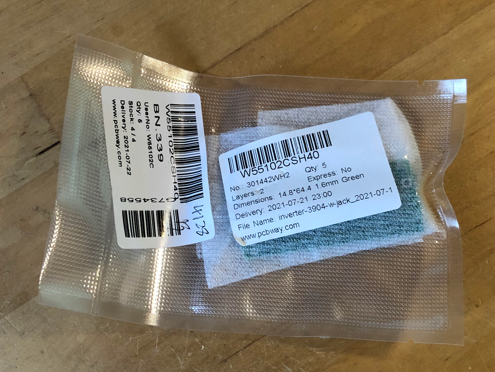
Here's the board packaged and ready to go, it arrived in the US 5 days after I ordered it.....go PCBWAY!


  The PCB I had fabbed for this modification is a very simple single NPN transistor inverter:

The output is high (V+ without R1 and R4 as a voltage divider otherwise) until the input 3.5"jack is  about > 1V relative to ground at its input, then the output goes low.  

Good news, the board worked first time--this is a simple circuit, I would have been upset if it didn't:

Layout for the inverter/buffer  


Working gate inverter/buffer


On a scope: output's high usually but we get a transistion to ground for each gate present at its input. 

Super Easy!  Here's a 3 or so second video.....output goes low when input goes high.


Let's Code! I wired the inverter to the dev board like this:

Simple!


And used this code--its a single main.c file.  This code works with the minimalist AVR 328 board posted here.

/*
 * ExtInterrupt_test.c
 *
 * Created: 8/4/2021 11:04:21 AM
 * Author : audiodiwhy
 */ 

#include <avr/io.h>
#include<avr/interrupt.h>

volatile int led;
ISR (INT0_vect)          /* Ext interrupt_zero ISR */
{
PORTB ^= (1 << PINB0); /* toggle DDRB PB0 */
}


int main(void)
{
        DDRB = 0b00000011;  /* PB0 and PB1 for output */
        DDRD=0x00; /*D ports are inputs; D2 and D3 are INT0 and INT1 */
        EIMSK |= 1<<INT0;  /* enable external interrupt 0 */
        EICRA |= 1<<ISC01; /* interrupt on falling edge */
     
        
        sei();     /* Enable global interrupts */
    while (1) 
    {
    }
}


Viola! Worked. Each gate's rising edge lights or extinguishes the minimal MCU's built in LED.  So I made a somewhat overly complex and fancy flip flop. Good enough.


Now I'm ready to pull the DLFO out of the rack and try to add the interrupt code and inverter PCB/input jack'buffer to it. Note: older post about interrupt for the Arduino Sketch world is here. 

I figure it will be an easy mod, but who knows? 

Thanks again to PCBWAY for out helping out.  I've been schtooping this blog along for a few years now, and in case you didn't notice, I need all the help I can get.

We'll finish L-FOTUS INTERRUPTUS Dirty Digital LFO next time.  Update: modified DLFO post is here.   Update to the update, 10-31-21: Rev 2 of the LFO is here, which incorporates the interrupt subcircuit just discussed, as well as many other improvements.  


Synth Gates, Interrupts, and Arduinos; a Million and One Uses

Yes once again: more Arduino Control Voltage Fu.

Continuing from last time...I am focusing on another corner of the Arduino for audio world:  interrupts. The idea; your code is running, we want to interrupt things (say, a note has just been pressed) and have something happen (say, play a note). When you are done, go back to whatever you were doing (like, wait for another note).

With further ado: the coding examples here were tested on an ATTINY85. All the interrupt information you see is available for most if not all Arduinos but the code will be different (because, for instance, a Nano has more than 8 pins).

Goes like this: When I started using Arduinos for Synth DIY, it quickly became clear I needed to figure out a good way to accept a gate input signal and control my code with it. Duh! We synth guys use 0-5V gates all over right?  But let's not create a loop like this: did someone press a key yet? No? How about Now?  No! Um, Now?  No!!!! Now?  Yes!!!! Etc. all that waiting around ends up sounding, well, not very musical.

Instead, you want to press a key, and then as close to real time as possible, you want something to happen.

So: what's a really good way to do this? Use interrupts....specifically change pin interrupts--then using a boolean variable to trap if the gate signal was going from 0 to 5V or from 5V to 0. That worked great for me.

Turns out it's not hard to stick all of this into your ATTINY85 sketch, once you know the secret:

First declare this:

void setup()
{

    // (pin declarations, variables, whatever blah blah....
    //but then this...

    GIMSK = 0b00100000;    // turn on pin change interrupts
    PCMSK = 0b00010000;    // turn on interrupt on ATTINY pin PB4
/* you can enable more than one pin for this.....
 a "1" in the above PCMSK line means use pins as interrupts, following this logic: 0bxx54321 where
the "54321" business are physical pins on an ATTINY. 
*/

    sei();                 // enables interrupts


Wait a minute, what are "pin change interrupts"? Information is here but: Easy! 

That means, you're using external hardware interrupts--change the voltage present at this pin, relative to ground, and you can immediately change what your Arduino is doing.

Added bonus: with "pin change interrupts" you can pick the pins you want to use for interrupts. Including more than one or two or three pins on the same chip at the same time. And, depending on the Arduino you use, the pins allow you create up to 3 completely independent interrupts, each of which can do something different! Handy!

BTW, an incredibly good explanation of the the Arduino interrupt universe--from the Atmel ATTINY to the big huge crapping ones--is here.

(The "change pin" moniker threw me for a bit. Shouldn't it be a "pickyerown" interrupt? Whatever.)

OK after your GIMSK PCMSK  etc. you have declare an "interrupt vector"--this tells the ATTINY what to do when the interrupt is thrown.

Here I am reading whatever voltage is present at PB4 pin and assigning it to "gatemaker", a boolean variable I do declare.


void setup()

volatile boolean gatemaker = LOW;

// blah blah, other stuff here....

ISR(PCINT0_vect)
{

     gatemaker = digitalRead(PB4);
}

This code can thus act on incoming data--a gate rising edge, a new midi note on, etc., fast--very, very fast. More musical!

So--do that like this and this like that:

void loop()

if (gatemaker == LOW) 

 // I see a falling edge, 5V to 0V, on my gate signal.  When I see that:

{ 
///do something; charge a cap, turn on an LED, change pitch, //whatever.....
}

//but if I see 0V to 5V......

if (gatemaker == HIGH)
{ 
//do something even still more different; discharge a cap, turn off //an LED, don't change pitch, whatever.....
}

Wow! That's really easy! A million and one uses: ARs, gate to trigger, trigger delays, on and on. Trap when your gate signal is going up or down, then do something fun. NNNNNNext!

Again this is useful for ATTINY but by studying Arduino coding on line can be done with all the chips I've seen in this large family--so, whatever other Arduino widget suits you.

This ATTINY methodology took me a few evenings to figure out, mostly because there are so many different documented ways to get at the interrupt paradigm, but this whole change pin interrupt/boolean method seems to work every time and is simple, simple, SIMPLE!!! For the Nano, there are two pins already all set for interrupts, and the code needed is the usual super simple stuff we all expect here in Arduinoland.

Back to Audio: Final thing to do is protect your ATTINY interrupt pins from an obnoxious gate signals from (say) your 15V power supply (oops!  Patched my modular wrong....blew up that ATTINY....magic smoke....yeh baby yeh!)

For that I used this circuit fragment plugged into the PB4 pin used above; as always, many ways to do this, but this simple NPN circuit fragment worked for me. Transistor is a 2N3904....this inverts the gate, so you have to code accordingly.


OK for now that's it. I created an ATTINY based module I call "ConBrio" allowing a gate to speed up up up or down down down. It uses this whole pin Change interrupt thing extensively. It works on the bench but I am trying to make it "more musical" whatever the hell that means. I figure I will finish the code and hardware for that and post it soon.

Until then, don't breathe the TINY and have fun!!!