Showing posts with label Noise. Show all posts

Noise! Lunetta Lunchbox--Done at Last!

Welcome back to the land of.....

 I started this Lunetta build maybe 18 months ago..... 

Finally done:


BLAH BLAH! JUST LINK THE SOUND SAMPLE!

if you want to hear the finished Lunetta synth, in action, soundcloud sound clip is here.

Boy Howdy! this started with a board swap with Reverselandfill.org (there is a newer version of Reverselandfill's NOISE! module, V8, here). The NOISE! Osc is a CMOS based chaotic sound generator, and right out of the box is a very cool build.... 

V6 of Noise!--older design, now it's up to V8

I built the original "stock" NOISE! module something like 16 months ago--it's a finished module--orig post is here:


But can never leave anything alone, so after discussing with Martijn, I created a not-for-sale PCB based on his original design, but sized to fit a smaller (non Frac) enclosure. Following that was a quad digital pot board controlled by Arduino (post here), a 4051 based mux board (again Arduinoized, post here), and a dual VCA board (post here).  I even used 3D printing to create hardware to mount the "stacks" (here)--3D printing was totally new for me. 


All that was left to finish this off was to create a power supply and a PCB to have blinky LEDS and to things power on--since there was leftover space on this latter PCB, I threw a 555 VCO on there. Why not?

Here's the psup, based on the usual PAIA linear design you find in fracs.


PSUP was quickly off to china for PCB fab; back, built.

The first Psup built kept blowing up (I mean BANG!!! and smoke, total destruction) the diodes used for rectification. I pretty much sucked every part off the board looking for the short but never found it, so I  built another. Of course: Second one, almost all the same parts, same everything, worked.

Wow--That Diode Blew up Real Good!


Why did the 2nd one work? No, not the missing reg. It was something else.


OK with the power supply temporarily not exploding, I next found that all the stacks combined drew about 150mA on the + rail and about 30mA on the - side. There were at least 2 instances of the + rail being dropped to 8V or 5V for the Arduinos. This meant that the 7815 regulator I was using got very, very hot, even with a decent sized heatsink attached. 

I didn't want the damn lunchbox thing to melt, so, what to do?  

At digikey I found this part:


I figure this part was designed for engineering amateurs and general bozos like me, who design linear power supplies and ignore any sort of heat loading. Very nice!

It's almost a magic part: a switching regulator that's a direct drop in for a linear regulator--with 92% efficiency, something like that? so no heat! and after putting that in (it was a direct replacement size wise for the 7815) the heat problem was gone.  

New problem though--powering everything on, the + rail would sometimes refuse to come online. After a few power ons and offs, it would come up. Strange!

Probably some filter cap issue downstream, but, whatever; I never figured this out, but just flicking the master power switch off and on a few times before using the lunchbox in the studio didn't seem like a big deal; I thought of it as an old motorcycle that doesn't always start the first time, right?

Last thing to build was a "jacks board" to hold things like the power switches, power rail LEDS and so on--since I had some space I threw a 555 VCO on there, but it could have been anything, here it is waiting to be mounted to the power supply.

"Every Project needs a 555"


I then got out the Antique rocket ship/jr. scifi lunchbox I bought on Ebay a few months ago--perfect graphics and patina for a Lunetta synth right?

OK, I dropped in all the boards etc. Good news: The 3D printing came out OK, it provided a tight enough fit that I didn't need to cut up the lunchbox to screw anything in, it's all just a press fit in there, and so far seems to be good enough.


Last thing to do is get it in the studio and make sure it all works. It does! Joy! No smoke!  No Fire! Bizarre sounds!

The synth is odd craziness as you suspect, but overall I think it's mostly good for atonal beep-beep-beep non repeating sort of stuff. Think of an alarm clock you seriously want to throw off a cliff? 

On the demo it's about 80% audio out from the lunchbox, but I also have the lunchbox providing chaotic CV to things like a Rings module. Like the original NOISE! it seems good for both audio and CV.

As far as posting allo the schemos etc etc--well, there is a ton of PDFs, eagle files etc etc., I will just make a giant ZIP of all of it and post it soon. UPDATE: 8-22-20. Eagle files and other "as built" docs are now posted.  Go to my website here. I will try to add scan and add PDFs down the road.

Many thanks and big shout out to Martijn Verhallen of reverselandfill--thanks for the support and encouragement.

Wow--can't believe it's done.  

Enuf! There are bad fires right now in not so sunny California, so there are even more fumes to not breathe--don't breathe 'em. Hold your breath. 

Noise! Lunetta Circuit Part IV: adding dual VCAs for Audio Gran-Turing-smos

Back again. I'm stuck at home with damn covid Shelter in Place and it's raining. Fortunately the PCB fab shop I use in China is still cranking and I got another set of boards for my Noise! Lunetta stack last week.

Built 'em up rawhide. Worked first time.  Here's all 6 PCBs to date.  The little switch on the left chooses the overall frequency range.

The project so far.....

About Noise!: It's an ongoing project I've been building for many months. I've tried to keep things organic: I think some damn thing, crank it out in Eagle, send it off, get it back, solder it up and see if and how it works. Like the Winchester Mystery House this project may never be completely finished.

It started when Martijn Verhallen from reverselandfill.org and I did a board swap. I really got into his Noise! tone generator and started adding to it, my goal being a full Lunetta type synth for oddball sound generation (I refuse to call this "Sound Design").

Part I--where I build up the base VCO and logic board is here.  Part II: resized and revised, here.  Part III: Adding a quad mux, here.  I created a quad digital pot board and added it to the stack, here.

AD5254 based quad digital pot board, Arduino controlled.  Post is here.

As I was messing with the interconnected PCBs: patching the stack to a bench VCA frequently came up as strange repeating patterns of audio bleeps and blurps. In the mod synth world this is not quite referred to as a "Turing machine"; as Turing modules I've messed with (a popular one has a demo vid here) produce CV, not audio, and on my bench it's the audio patterns that tend to repeat over and over. But whatever. Is a frequency to CV board coming next? Perhaps.

So why not add a couple of VCAs to the stack?  OK, easy, I already have built up a 2164 based dual VCA board (here), I just needed to lay it out again to fit the 3750x2000 mil footprint I am using for the project.

Got em back, built 'em up. No dumb mistakes--yeh baby. You can get eagle files, PDFs of schematics, Eagle files etc. here.

OK now the bench photos--sorry--some folks take photos of their dogs and cats, but I don't have dogs nor cats, so you get circuit boards.

The 3750x2000 dual VCA board.  

Ready to test....

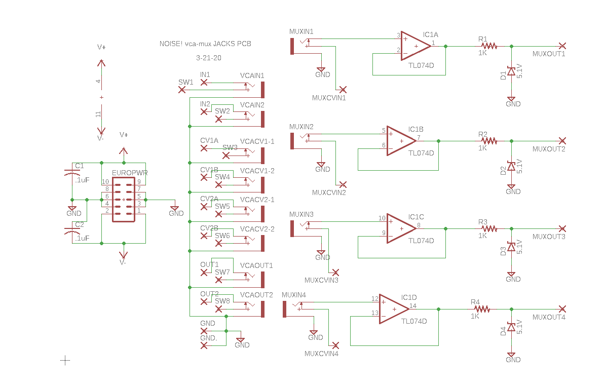
The front facing board is a jacks PCB for the 3750x2000 dual VCA. While I was at it I added buffered CV inputs for the MUX board using the usual opamp/zener thing.


I used the usual super-low-parts-count zener clamp/buffer to keep the Arduino CV inputs from frying:


However I am curious about this clever fragment I lifted from a Mutable Instruments design--looks to me like it allows more stages with only one zener reference; didn't use it this time, will use it down the road.


After that, it became a matter of wiring it all up and testing.

Ready to test!


OK so how does it sound?  I still need to record the damn stack for real but you can see a vid of some of the repeating patterns at work here.

Is it for everyone?  Nope. Time to keep moving. Might do a powersupply and LFO and call it done.  I guess we'll see.  Until next time, don't breathe the fumes.

NOISE! Lunetta Board--Part II--Lunetta Lives!!!

Life in Lunetta Land must be vibrant--my previous post (here) about a 4x Lunetta Oscillator based on the CMOS 40106 IC is one of my most viewed to date.

This time we carry on with part II of ReverseLandFill.org's Noise! Oscillator build (part I of this post is here), combining the AD5254 digital pot board from last time (here) with Martijn Verhallen's Lunetta design. Update: 3-24-20 I added a 4x Arduino controlled CMOS MUX to this--post is here.

Martijn did his usual great job on the initial board, but I can't leave anything alone....hence the digital pots. If you want to hear how the module below sounds so far: clip is here. I'll be adding more circuitry to this self-contained synth and will augment the clip in the future, but so far NASA we already have strangeness.


WTL? The concept of my "lunetta stack" is pretty simple--I slightly revised Martijn's original design (he was kind enough to send me Eagle files) to accommodate the quad pot board from last time (here) and then stacked a board on top of it to hold "tall trimmers" and Thonkiconn PCB euro Jacks. That gives us quick control over the CMOS 4093 oscillators which feed a 4040 counter. There is a 4070 XOR IC on the board as well but it's not wired to anything (yet). That addition will be coming one of these days. UPDATE: 4070 is now being fed by a 4051 mux....works.  Post is here.

To use the board, for now, let's just power up the stack and plug the output into our DAW.  That's what you hear in the demo--this is all Noise! w/ the quad pot CV board, and a bit of reverb or delay or other minor FX from the DAW so your speakers aren't ripped to shreds. And: the sounds you hear were not created with complex modular patches--just LFO and audio from a single VCO fed into the noise! circuits' various CV ins. Full disclosure: the Noise! board isn't a good fit for a traditional JS Bach revival concert but nevertheless, Martijn's cool design has yielded one of the strangest sounding modules I've built to date, and maybe that's not a bad thing.


The idea of stacking boards is not new--the whole idea of "skiff builds"is based on that; for instance, see the SEM attenuverter project here. For Lunetta work I am trying to standardize on 2000 x 3750 mil PCBs because that will fit pretty easily behind a 20HPish Euro and/or a 2u Frac; I want to keep things small. For this particular build though, I am thinking about putting the entire finished Lunetta synth into a goofy lunchbox, and maybe creating PCB front panels to live inside? not sure yet....that's something for an upcoming post.


One thing I did find out is that #4-40 Phillips screws aren't easily found longer than 2", but I guess that's OK, how big should this stack be, really?

Tall trimmers, available from places like Modular addict, drop into appropriate 9mm 90 degree PCB pot pads. You can cram a lot of pots into small spaces with these things, but make sure to leave room for your fingers....


Schematic is from Martijn; he tells me he was inspired by E-M designs and this book.....slightly modified, but at its core it's all MV!


Dirty Pun omitted! The jacks board is mostly for convenience--debugging and troubleshooting would have been a nightmare with jacks and pots flailing all over the bench. Not sure if I will reuse this "jacks PCB" for the final version of the stack--probably yes but who knows.  Update--read Reverselandfill's post about this post here. Go reverselandfill!

OK what next?  The CV ins for this sound extra bizarre with DC VCAs in series, so I designed a 2x VCA board in 2000x3750mil for that, but it's still off at fab. Same with a 4x 4051 CMOS switching board that I will use between the main board's VCOs and some additional outputs. (Update--4051 MUX board is done and works. Post is here)

Those 2 boards, added to the project, should further add to the unabashed craziness I hope.

I'll do a part III for all of that, but as it sits this Lunetta setup is already pretty fun. With a few more boards in the stack and this thing hot but not smoking I'll eventually post all of this on my website including instructions about how it's wired up, but for now it's still a work in progress.

On a minor note: one of my 3340 VCO builds smoked a couple of nights ago--still not sure why--I am still breathing the fumes--this mishap didn't burn down the house, but stunk the hell up out of my project studio. Let's hope today's project doesn't suffer the same fate.


Reverselandfill.org Noise! Part I: Making Noise!

Welcome back! Last year I did a PCB swap with Martijn Verhallen from Reverselandfill.org. Fun!!

Martijn specializes in industrial electronic music and video synthesis and always has some very cool boards at his site.

Last year I built a module based on a reverselandfill design that Martijn calls "Aconitum Noise Mixer". Never being able to leave anything alone, I modified it using some C1406HA's, a oddball and somewhat obscure stereo panning SIP IC, which I put into play as a quad attenuator.

I am happy with how this DIY module came out--you can read part I of my Aconitum build here; part II is here.

This time I get started on the second PCB Martijn sent me. After sitting in my PCB box for many months I figured it was finally time to build his Noise! Oscillator design. Here we go!

Rev B of the board--Rev C is current--what I get for letting the board sit in my to build box to long!

About the Noise! Osc Board: You can see the schematic for it here; here's a basic flow chart of how his design works:


It's quite a different approach to noise creation compared to the "lifted leg transistor" upon which Martijn based his Aconitum design. Noise! is more of a random tone generator then part of the analog white/pink noise hegemony.

The noise osc board at its core relies on two popular CMOS ICs known to Lunetta enthusiasts everywhere: the 4093 CMOS Schmitt trigger and CMOS 4040 divider. As usual, Martijn has conjured up a creative and musical board!

An interesting feature of the board I've not seen before is what Martijn calls "starve". The idea is to crank down the DC voltage feeding the CMOS ICs. That will greatly change the sound of the device (and it does, I've tried it). 1001 uses? Interesting (and easy) thing to try on any CMOS audio creation perhaps.

For 9V use a jumper; for starve action, use a pot.  Interesting results!


For this post I will get the basic PCB working; down the road I will automate the board's patch bay for added voltage controlled craziness.


About the build: The Noise! Oscillator is well documented and uses easy to find parts, so stuffing the board was a breeze. I populated the board (it is sized for Eurorack; I use FracRak so some shoehorning will be in order) and created some 3.5mm audio I/O PCBs for testing. I've been using Switchcraft RAP2AV's more and more lately; they are reliable, solidly built, and perfect for slapping together something to mess with fast.  


For power (for now) I am using a 9V wall wart from my junk box. If everything works I will convert a 15V rail from my power supply to 9V.  More on that in an upcoming post.

Good news: I put in the chips and caps and whatnot and the Noise! Osc board worked first time. But of course I'm never happy with that (too easy right?), so I got out my rework station to try different cap values and different pots to see what would happen.

Sadly I sucked up a couple of traces when messing with the pots which took me a couple of hours to diagnose and fix. Damn! As I am writing this post I am still messing with the RC values for the oscillators.....I also tried adding vactrols instead of the pots (which didn't seem to work that well) and ended up settling on a single vactrol in parallel with the leftmost 100K pot. 


Ah!  Now we are ready to test. Each 4093 based oscillator has CV control; with my vactrol addition that's 5-count 'em! 5 different CV's for some very odd noises. 

OK, the basic build works and small pot and CV adjustments go a long way with this board.  I'm happy so far--I've never heard anything else like the noise! osc and it will be fun to create some audio samples when it's 100% done.  As usual, hats are off to Martijn. 

Coming up: I have designed and sent a gerber off for fab to automate a 4051/4066 CMOS based patch bay. I have no idea if that will work or how it will sound once it's in play. 

UPDATE: (5-11-19) OK it didn't work. The 4051 switch board for Martijn's board had a lot of the same design errors as the Con Brio Arduino board. However unlike ConBrio, the patch bay board for this sucked so bad I had to pitch it....I am going to redesign the patch bay board and try again.  

UPDATE: (8-17-19) Fiddlesticks! Still not happy with the 2nd gen MUX board. I know I can coax good craziness out of this board--I can hear it manually patching, but I want to audio-mate!!  I also think I ruined the PCB trying more vactrol mods and sucking up more traces. Crap!!!  But I will not be defeated! Stay tuned!

UPDATE (2-26-20) Part II of this post is here--still no mux, but i did incorporate CV controlled pots, and we have more crazy sounds!

UPDATE (4-5-20) Front panel for what you see here is done. Uses PCB material for the actual panel (post here) and "Mr Label" for the artwork (here).


So: lots more work still to do for this one. After about 8 hours work on this build today, it's time to stop breathing the fumes. Until next time--Aloha!

ReverselandFill "Aconitum" Noise Board--Augmented with C1406HA VC Attenuation--Finished!

Hello again fellow readers and audio nerds.  This post: Time to finish off the Reverselandfill "Aconitum" board for my DIY modular synthesizer.

If you want to skip what's below and just hear what the module sounds like finished, that's here.

Also: Part one of this post is here. You are going to want to at least skim the first post or the rest of this one may not make much sense....

Getting to it: after a PCB swap with Reverselandfill's Martijn Verhallen he was nice enough to send me the eagle schematic for his analog noise mixer so I could understand how it works.

His "Aconitum" noise board is designed something like this (it's more complicated, but this is the basic idea):
Simplified block diagram of reverselandfill's Aconitum noise board

An NPN "avalanche" transistor gets sent through a couple of extremely musical passive variable filters, then mixed with two inverting op amp stages in series. There are accommodations for jacks and pots on the PCB, making it a good fit for your Eurorack modular synth.

NB: Martijn must have worked really hard on this design...."box stock" it's a really good sounding board. The filters yield extremely useful timbres for things like rain, wind, surf, everything between, all the way to frying bacon and back.

But "in spite of good tone, I can't leave anything alone?"  For extra headaches I stuck C1406HA attenuator SIPS in series and added a 4th input for external sounds like this:

I could have used VCAs for this.... but trying something new was more torture and thus more desirable.

See more about C1406HA's from my last post about this project; in general the C1406 is an easy to implement voltage controlled dual attenuator SIP IC--in goes audio and CV; out comes audio levels based on CV--the more CV, the more attenuation.  It's like a VCA that can only cut amplitude, not boost it.

One of the challenges for this build (other than some bonehead mistakes on my PCB--more about that in a bit) is that I use FrakRac and Martijn, like many more sane DIYers, uses the much more popular Eurorack format. So I had to piggy back my board below his to make this fit in my rack:


Thank goodness for 4/40 hardware?


Once I got all that bolted together, I separated out the boards and panel and got to work with stuffing and wiring them.

Aconitum board is on the right; my custom panel and quad attenuator PCB on the left.

Let's get building (finally): First I wired up the Aconitum board and powered it up so I could hear it:


Good news here: Martijn's board is flawless--no mistakes--nevertheless, he emailed me a few times to say he is improving it....cool! Martijn also PM'd me to say that he owes the legendary Thomas Henry and Ken Stone for design ideas for the Aconitum board.....if you get your hands on this board, for me it worked with +/- 15V without any mods, even though it's designed for +/- 12V.

Next I wired up my REV1 C1406HA quad attenuator PCB fresh off the DHL boat; and this is where my problems began:

The original schematic--anyone interested, I will post it in Eagle and PDF....


C1406board Rev1: a Plague of Locusts.  Here I've already fixed the power silkscreen issue.....

I rushed this design and fab and made some really stupid mistakes:

  • the V++ and Ground silkscreens on REV1 of the board are drawn backwards. Really?  Um, yep! Traces are OK but the silkscreen says to wire the power supply's V++ to Ground and visa versa.  Doh!! Nothing blew up, but my board obviously didn't work at all until that was straightened out. It took me an evening of head scratching to figure the errors of my ways....it was such a dumb mistake it took me a while to realize, hey, everything is backwards!
  • I forgot to put 100K resistors at the "output side" of the 1406 output decoupling caps. Since these caps are tied to a TL084 (super high impedance inputs right?) there was nowhere for the current to go so the decoupling basically didn't work at all, and I still had a DC offset at output. That's something my first tech boss always told me: always give current somewhere to go!  You'd think after 30 years I'd get this right, but, nope. OK kludged some 100K's on the bottom of the board....now the cap coupling works--fixed.
  • the C1406HA can't really support 10V P/P.  So its input needs to be gained down, while its output needs to be gained up. That remained unfixed; I just have to watch pegging the C1406, but I guess sometimes the pegging doesn't sound that bad (but often it does).  I'll put 6db gain at output I think on the next run. See R21 circled below--this is the standard 6db gain op amp configuration, that's the idea.

Some schematic detail about the resistor issue:


You need resistors R13, R14, R15, R16 to have upstream capacitor decoupling work!

...but my original design was what you see circled in blue, non inverting buffers....which didn't work.


OK I kludged/fixed all those mistakes.  Yes it's a pain to have to kludge prototype boards, but perf boarding all this would have been way more work.....

For those who want to share the pain: I have a revised board ready to be fabbed--as usual, any takers on trying the improved one out? no takers? OK I will get to checking REV2 one of these days, but the REV1 board works, anyway, after I have fixed all the DUMB ASS MISTAKES. I might make a smaller stereo version as well....

Moving on:


I wired the two boards together--a lot of wiring, but nothing too difficult.  

All done but no panel decal; ready for testing

The good news is after all of this I got (I think) some really good sounds out of this board.  Take a listen on Soundcloud here.

Details about the demo:

As usual the demo was made fast, fast, fast.  If I can do this in a few minutes, you should be able to better in say 15 minutes right?

00:00 to 00:28
: Surf part I. Each noise source in Aconitum went though an its internal passive filter then through the Aconitum's built in mixer. The wave crashes were produced by a slow random gate generator which was fed into an ADSR, which was then used to produce CV; that CV attenuated noise ("Tone1") using a C1406HA CV controlled attenuator. Tone1 was set to a very bassy, boomy filter sound. NOTE: I cheated a bit on this one: a tiny bit of phase shifting, reverb and bandpass filtering was used in series with the output to make it the aconitum sound a bit more "other world" but you can get good surf sounds stock right out of box (listen to the last cut of this demo?).

00:30 to 00:45: LFOs feeding the 1406 attenuator. Each of the 3 Aconitum noise sources had a different LFO input attenuating noise. The output of the Aconitum's mixer section went into a vactrol bandpass filter, getting rid of very high and very low frequencies so your speakers and ears aren't destroyed.  With some screwing around I probably could have gotten close to the Apocalypse Now "Helicopter Whup sound", maybe for another day.

00:45 to 01:00 same thing as 30 to 45, but different LFO settings. The "sprinkler" sounds were created by using a CV controlled LFO.

1:05 to 1:30: I put a drum machine snare and kick outs into envelope followers and used that to trigger ADSRs which fed the C1406HA attenuators. The kick and snare noise sounds you hear are substitutes for a 707 kick and snare. The hat sound was fed into the "external" attenuator channel and passed through to the aconitum's mixer.

1:35 to 1:45: A byproduct of setting up the gun range sound (which comes next). Fast Random gates hitting the noise attenuators and also throwing the sound into a stereo panner that was very quickly panning between L and R channels. Produces a frying bacon sort of sound.

1:45 to 2:15:  The gun range. Each output of the aconitum (noise, tone1, tone2) was fed into 3 VCF's and 3 VCA's.  The VCA's were modulated by ADSRs, each of which was driven by its own random gate. this went into an external mixer and into my recorder.

2:15 to 2:40: Same as 00:00 sound but I changed parameters to make it sound more like traditional surf.

BACK TO THE BUILD: Final step after testing and seeing what it can do was to decal it.  


Ok that's it for now.....Overall this modified board swap module was a lot of work but I had a lot of fun building it, and it's already become a really useful addition to my DIY modular synth. I think it sounds really good!

Not sure what I will work on next but the MCU world is calling me again. My girlfriend (who btw is a mental health professional) says I have become too obsessed with DIY, and I need to take a break, so I am almost done w/ week one of a two week lull.  Did I breathe too many fumes? Maybe! And always remember: "Sanity is relative".