Monday, January 30, 2023

AD9833 Audio VCO--Works But not Finished


 I finally have the AD9833-VCO working! Eurorack format!

The fun starts with the AD9833 post here. I wrote a C library for it....then I did this thing with the AD9833, then this thing, then that thing, then something else--oh I have to link all those posts?

Nah, if you want to know the history of the function generator IC used in this VCO, please search this blog for "AD9833". 

This blog is chock a block full of posts about this handy little IC--I have written more about this function generator IC than I should have? Why? 

To cut my teeth on embedded C, SPI, UARTs, and everything else we know and sing. 


WORKS, BUT NOT FINISHED!

This has been a laborious project--as always, still, more work needed....

The 12-bit Seeed ADC buffer board--good for a lot of projects--may not be the right solution here. Best I can tell, 12 bit data gets lost in the A-D noise floor (I think?) and thus the audio output of the VCO is a bit jittery. I want to fix that. I could use a 14 bit ADC and just toss out the 2 LSB's. That might help?

Also the triangle to ramp PCB's ramp output (previous post here) a bit too buzzy sounding. There are ideas on Muff Wiggler about ameliorating that puppy.

For now it works, the VCO doesn't smoke, looks OK, tracks V/octave fine, and damn, I need to get this Rube Goldberg thing off my bench for a bit!

THE SIGNAL FLOW:


I mostly designed and built this VCO to see if I could figure out how to design and build this VCO. Makes sense right?  There are lots of designs out there for audio synthesizer VCOs that are a lot simpler. This isn't one of those.

How it works:

Input is a volt/octave CV, modulation CV, and a frequency and fine control.  

These are mixed, buffered and clamped by the buffer board that incorporates a SEEED XAIO RP2040 dev board (previous post here, the buffer PCB is a PCBWAY community project; PCBWAY sponsors this blog--thanks!--if you want to build one, you can get the gerber here).  

The RP2040 on the SEEED dev board is running embedded C (current code revision of the code is on Github, here).  

It uses a python frequency lookup table array creator--which I turned turned into a .h file for this project (github repo for the Python array frequency creator is here). 

I also used the AD9833 C library I wrote for AD9833 (github here) and debugged using UART (post here). SPI is used to drive an AD9833 (again, lots of posts about this IC, for the VCO I used this cheap breakout board).  

The AD9833 has a 600mV unipolar triangle output--so yet another PCB is used to convert the triangle to ramp and pulse/PWM and buffer the 3 signal outputs....post for this subcircuit is here, modwiggler forum thread about the concept and design of the converter begins here

Yes, this is a complex build!  To make it even harder, the build uses no hookup wire and is configured in Eurorack skiff format. That makes it harder to modify and troubleshoot, but, well, who likes things to be easy?

Build Photos:

Board fab was from this blog's sponsor, PCBWAY--please help out this blog and check 'em out.


testing the triangle to ramp converter....it works....


OUTTRO


I blew up a SEEED dev board getting this going, one AD9833 BoB was defective, and one SEEED board was DOA. A lot of swearing and head scratching has gone into this project so far.  

This experience has been pure DiWHY--such as, why am I building such a complex VCO when a 3340 based analog equivalent will probably sound better and be a hell of a lot easier to lay out and build?

Because it's there?

DiWHY masochists: show you can take the pain and get yer zips for BOMs, gerbers, PDFs for the schematics and boards, and Eagle CAD files, at Github here

If anyone wants to join in with further madness, message me through the MW forum and you can play along. or just grab the files and start modifying.  

In the meantime I am going to take some time off DiWhy--my pychiatrist fiance (amazing she accepted my marriage proposal right?) tells me I need a break. The Good Dr. is always right.

work on other projects for a few weeks or more to regain my DiWHY sanity. 

Then go back to this project. 

For instance, I already have a 14 bit ADC board to replace the 12 bit version used for this project. To skiff-ize the PCB, it uses a lot of tiny tiny SMD parts...should be a real pain in the butt to fabricate. Blah blah ginger blah blah?

....this project tied a lot of previous learning into one module, and getting it to perform better (better sounding ramp, better ADC performance, other improvements) will be good learning as well. I will say it yet again: in the words of immortal Emil Faber: "Knowledge is good"
 
Update 3-5-23: newer version of this VCO is here--greatly improving the design--in spite of all the whining.

Back to work.

Thursday, January 19, 2023

Improved SEEED RP2040 Buffer Board--Mutable Instruments Homage

Hi there, continuing to work on the AD9833 volt/VCO, it's raining endlessly here, I am in a crappy mood, and man I am getting tired of this damn VCO build. 

Ah yes. The RP2040-AD9833 audio VCO. Is it done yet? can we pretend it is?  Update 3-6-23: It's done and came out rel good! Thanks to these guys for support; more about the finished + working AD9833 based V/octave VCO here.


For the ADC and analog buffer portion of the VCO I lifted design basics from Mutable Instruments, who make fantastic open source synth modules:

  • MCP6004 low cost quad rail to rail op amp for analog input buffering and clamping
  • Unipolar operation for the op amp
  • Inverted input from buffer to the MCU (why not--saves parts--fix this in software--gotta love Mutable!). Everycircuit simulation of the idea is here.
  • Zeners for most of the voltage regulation--cheap and simple
  • a fifth 12-bit inexpensive ADC in addition to 4 provided by the RP2040 MCU (I'm not counting the on board ADC used to measure MCU temperature which isn't needed for the VCO)
  • other general improvement and fixes to my initial design stupidity 

I did a post for version 1 of this same idea (here) but it sucked, this version irons out a lot of kinks.

Get this buffer board--a dev board for a dev board?--from my sponsor's PCBWAY's project page, here.  You can also get gerbers for a lot of other AudioDIWHY projects from their community pages.

You will need the most excellent and very tiny SEEED XAIO RP2040 board to make it go.

 
Some improvements to the previous version of this buffer board:

  • Jumpers to enable digital or analog (JD0, JD1, JD2 on the schematic) for the the D0,1,2 MCU pins.  
  • Ground pour for bottom PCB copper (imagine that)
  • a 10K timmer and 96.7K resistor in series, along with a 33K resistor for the opamp's negative feedback, to get us very close to the necessary 3:1 ratio for incoming voltage to the dedicated ADC IC
Using the jumpers:
  • If you want to use a given op amp buffer stage, connect its two corresponding jumper pins.
  • If a jumper is disconnected: to prevent the unused op amp stage's output permanently slammed to its V+ rail, put a modest voltage (say 1/2V) at its non-inverting input.

Let's build it:

Happiness is a white box o' boards from this blog's trusty sponsor, PCBWAY:

Thanks as always to PCBWAY for sponsoring this blog....please help this blog and check them out.


Running the default blink sketch the whole thing worked first time and drew 40mA for the positive rail. The current draw from the older version was more like 150mA. Wow!! There must have been a stupid mistake I missed on the last iteration of this board, making it draw too much current.


Se habla blink? Claro que si.


We are ready to use this board for other projects!

More more MORE pcbs for the AD9933 VCO. Again: Are we done, yet?

Using the board should be straightforward.  If you are using ADC 0-1-2 (on the RP2040) you need to jumber JD0, 1, or 2 accordingly.  Otherwise, to use a digital in instead of buffered analog, leave JP0, 1 or 2 off. Also, if you are not using a given op amp stage you should leave C6/R10 (ADC0);  C7/R11 (ADC1); and/or C8/R12 (ADC2) off the PCB.  In this configuration, the unused buffer will get the -10V input signal which will keep the unused stage from flopping around at its output.

Onward....

Being a glutton for punishment I laid out pretty much the same board with a 14 bit ADC. Will it work more and better? We will see in the next few posts...but hopefully this damn VCO this board is going into will be done before the next global extinction event.  Update: With the VCO working the 12 bit MCP3201 ADC cuts the mustard. This was unexpected? So....for now the 14 bit version remains  unpopulated, but it will see life--assuming it works--in a future project.

Until then: Don't breathe the fumes--always bite off more than you can chew--stay in vegetables--eat your school.  

Sunday, January 1, 2023

Happy New Year--Happy New ToolChain--APIO and TinyFPGA-BX

Hard to believe it's already 2023. Time flies when you’re having fun--and flies faster when you're being geeky.  

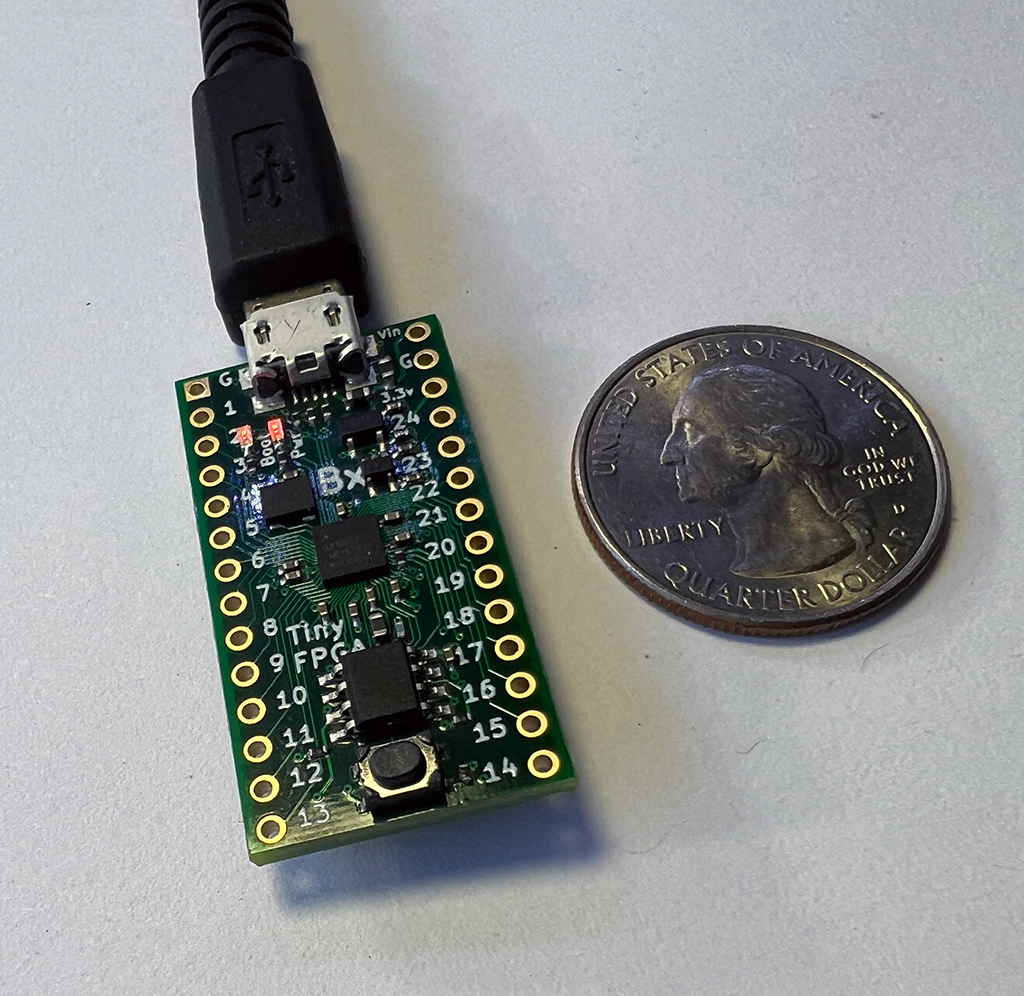
A year or so ago I bought a nifty dev board--the TinyFPGA-BX. It gets good reviews, is well documented and relatively affordable ($38USD).  

I figured this board would be a good starting point for learning, then using, FPGA's

FPGAs are the cool ICs where you can create your own logic "from scratch".  More here. But I know zilch about using these parts for AudioDiWhy. And I see a lot of cool FPGA use cases out there.

Almost zero knowledge is almost never good. Let's start trying to change that....

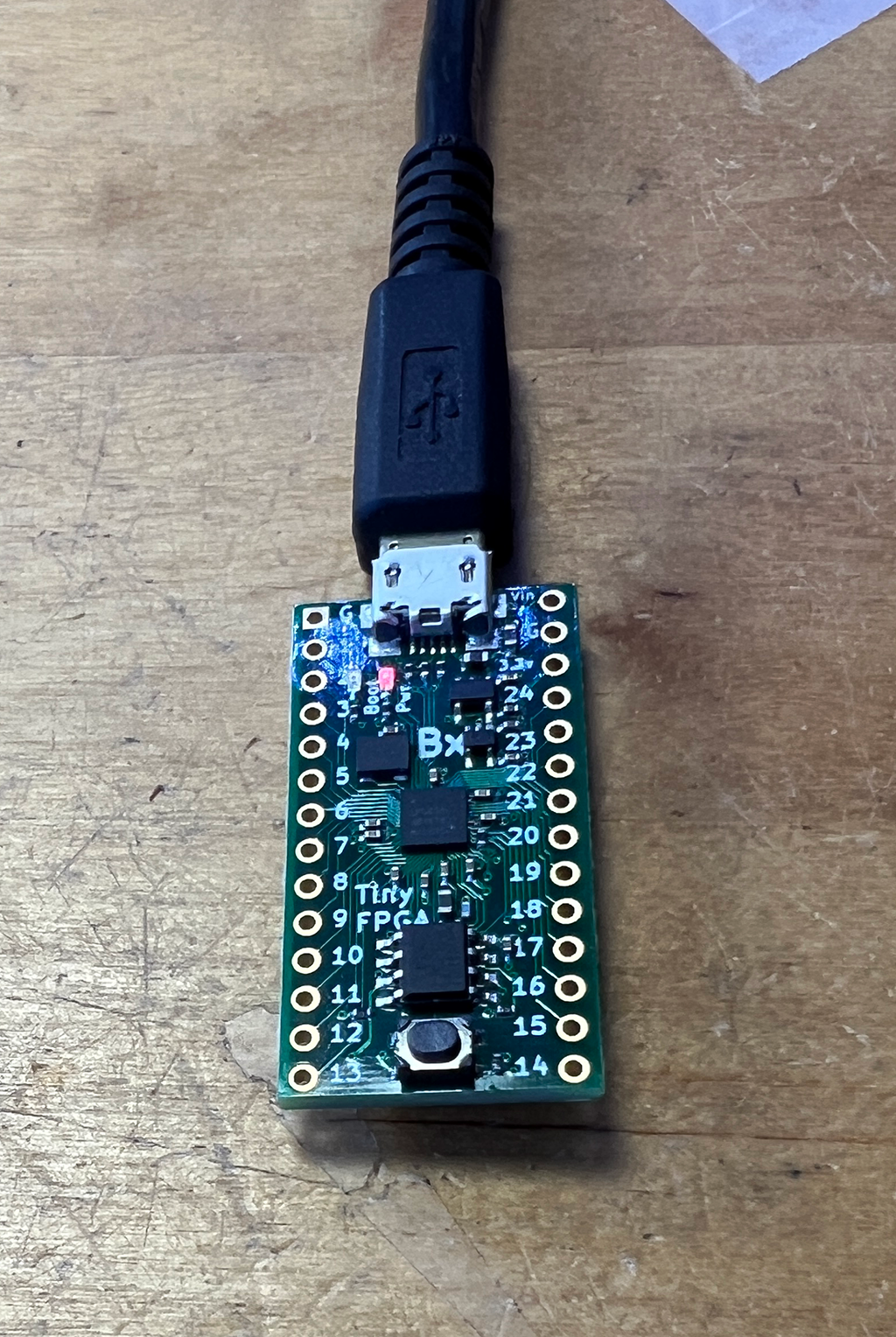
The TinyFPGA is indeed....tiny....

The New Year started with a long weekend--which means--time to plug in this FPGA development board and install a Toolchain.

Hours of Fun! 

But! The FPGA paradigm--hardware, software, all of it--was brand new for me--I needed guidance. 

YouTube. Of course.  

Shawn Hymel has an excellent (as always) video series about FPGA's, I started there.

Part I summarizes what FPGAs are and what they are commonly used for.

Part II goes over setting up the toolchain for Icestick....a development board very similar to the TinyFPGA-BX. 

Good news….Both Icestick and TinyFPGA-BX are supported by APIO, a popular open source development platform for similar FPGA's. So I set out getting that going....Getting APIO working was the crux of the biscuit:

GO APIO!


I decided to install APIO on Windows, not Ubuntu. I thought it would be easier to find help if I got stuck--Shawn Hymel, as well as many other users online it seemed, used Windows for this toolchain.

Apio relies on Python.....I have Python 3.11 on my Windows system--the latest Python build as of this post.  

I also installed Apio 0.6.7, not the latest Apio build. Shawn recommended using this older version.

For editing Apio project files I used Notepad++ which has syntax highlighting for Verilog--nice. Hint: if you use windows, run, don't walk, and get Notepad++.  A million and one uses!

The proof of concept for the toolchain setup was to get get a blink going on the TinyFPGA but at a frequency faster than what is found in APIO's examples.  Getting the basic blink should be easy--just load up APIO's example. But would it blink faster, Scotty?


TOOLCHAIN BASICS

I followed the setup steps in part II of Mr. Hymel's video--as well as steps found on the Apio website. 

I won't repeat all that here, please watch the video and read the webpage.

I had to make a few changes; not sure if it was because I was not using an Icestick, rather a tinyFPGA; using Python 3.11 and not an older version; using an old version of Apio; or something else.

I was using a different FPGA dev board so I used this to initialize my FPGA board:

apio init --board TinyFPGA-BX

When I tried to build an the example Blinky project, Apio would throw an error I didn't record--something about an issue with Python's click module

(Aside: Python click looks totally cool! I didn't know about this module! I am going to use it in future python projects....)

I guessed Python 3.11 was too new for the 0.6.7 version of Apio? Speculation....

Based on this hunch I upgraded to current Apio--cmd as local admin:

apio upgrade 

It still didn't build! 

It threw a different error; Apio told me to add tools-os-cad-suite. Perhaps this tool added functionailty needed for the TinyFPGA-BX. Not sure. Guessing still.

Again, I didn't record what I used to install this add-on, but the error message in Apio told me the exact syntax needed to install the tools-os-cad thingy. 

Fixed? 

Yes! Afterward I could "synthesize" a simple "Blinky" example:

apio build

Progress!  Synthesis seemed to work!

UPLOADING BUILDS 

Once the blinky code was synthesized--like C getting compiled I guessed? getting the dev board to eat code was next up.

Unlike the Icestick, the TinyFPGA-BX did not use an FTDI chip for USB to Serial. Instead it used tinyprog--some of the FPGA's gates do the USB to serial translation, not an external IC

This must have been a ton of work for a very skilled FPGA developer....You can see python code used to call it here. Very cool stuff.

But the damn thing still wouldn't eat .v files:

--tinyfpga not found

However running tinyprog -m  from elevated command prompt, yes, the dev board was recognized:

C:\Users\audiodiwhy\Dropbox\FPGA\apio-projects\tinyfpga-bx\BlinkyCL>tinyprog -m

[

  {

    "boardmeta": {

      "name": "TinyFPGA BX",

      "fpga": "ice40lp8k-cm81",

      "hver": "1.0.0",

      "uuid": "482fefbb-c6ce-4e08-aab8-84f55c23f788"

    },

    "bootmeta": {

      "bootloader": "TinyFPGA USB Bootloader",

      "bver": "1.0.1",

      "update": "https://tinyfpga.com/update/tinyfpga-bx",

      "addrmap": {

        "bootloader": "0x000a0-0x28000",

        "userimage": "0x28000-0x50000",

        "userdata": "0x50000-0x100000"

      }

    },

    "port": "COM3"

  }

]

Hello? 

I found a support page here--others with the same issue. 

The workaround:

  • run cmd as local administrator
  • cd to the directory of the project
  • run this instead from elevated cmd prompt: 
tinyprog -c COM3 --program hardware.bin   


COM3 had to match the com port found in the tinyprog -m output.

not sure why but--that worked!

MODIFYING THE .V FILE

In reboot mode the tinyFPGA had an LED-off fading to a LED-on, I wanted to create a more rapidly flashing LED to prove the toolchain worked.

Verilog isn't a programming language, rather a hardware description language.  Either way, I knew zilch about how to do anything useful. 

After making some random changes that made the LED go off (or change states so fast and slow it seemed like nothing was happening) I read a tiny sliver of how Verilog actually works. Imagine that! 

I eventually stole the fix from another web page, here.  

This .v file did the trick:

module Test (

  input CLK,    // 16MHz clock

    output LED,   // User/boot LED next to power LED

    output USBPU  // USB pull-up resistor

);

  // drive USB pull-up resistor to '0' to disable USB

  assign USBPU = 0;

  reg [19:0] counter = 0; // was [24:0]

  always @(posedge CLK) 

    counter <= counter + 1;

  assign LED = counter[19]; // was [19]

endmodule

From my limited understanding, [24:0] in the original Blinky sketch set up a 24 bit timer. I figured 19:0 would be faster since it's a 19 bit timer. It worked--the blinky blinked must faster.

UP AND OUT!

OK that's almost it for this time. 

I have a working toolchain for FPGA! 

I am still waiting for boards to come back from my loving sponsor, PCBWAY, (see, Wendy, I still got the plug in....)  But they aren't due back for another few days.....

So more coding, less fumes? If I have time, I will try to learn a few more things about Verilog.  

Onward! 

Until then, have a Happy Geeky New Year!

A guy OK with C tries to learn C++. Bjane me Up, Stroustruppy!

Why no posts so far for 3-2024?  I have been woodshedding, brushing up on C++ skills.  What got me to finally start digging into C++? I was ...