Readers: If you'd like to build the project featured in today's post, please go to PCBWAY's Community pages--a gerber ready to download and/or fabricate as well as KiCAD files and a BOM are here.
Also please visit PCBWAY's site--using the link here--it will help this blog immensely. Thanks.
====
Last post I described a subcircuit that would take an audio signal from maybe 50K to below audible frequencies and turn it into a square wave--useful for turning audio into a clock signal for an MPU.
It worked, but discussion ensued at my geeky audio meetup: is there an easier way to do this?
Of course there is....Elton at OtterMods had a similar circuit, with lower parts count, based on an LM311 comparator.
This post I'll discuss Elton's design, the LM311 comparator and build a prototype break out board ("BoB").

The Design:

How it works....
D1 turns a bipolar input at J1 into a signal at 0V and above.
That's fed into the inverting (-) input of the LM311.
The non-inverting (+) signal is the reference, with 12V for Vcc, the 47K and 10K divider sets pin 2 at about 2V.
R5 sets the duration of the output signal.
The LM311 needs a pullup resistor (R7; 1K) while the 2N7000 FET and R6 re-inverts the output.
About the LM311


A pullup resistor at "Collector Out", 3VDC to 15VDC at Vcc (pin 8), GND at pin 4, and a reference voltage (can be ground presented at pin 3, the non-inverting input) is all you need; let the balance and bal/strb inputs float; finally, tie EMIT OUT to GND.
We are talking 2 components: the IC and one resistor, to get a fully working, reliable, fast comparator.
 |
| The 2 component comparator. For the pull up resistor: 10K should work. |
A few more LM311 benefits:
- Vcc to Vss can be 36V apart before you blow up the IC. Since we synth and audio nerds often work with +/-12V or +/- 15V for our voltage rails: good fit.
- Simple operation--if the non-inverting voltage at pin 2 exceeds voltage at pin 3, the output (pin 7) goes from hi-z to low.
- Unlike an op amp, the 311's the inverting and non inverting-inputs aren't virtual grounds--you can see the incoming signals on pins 2 and 3 with a DVM.
THE BUILD
Elton emailed me his schematic and I laid out the schematic and PCB in Kicad.
I created a gerber and off it went to this blog's patient and enthusiastic sponsor, PCBWAY.
In a few days PCB's were in my mailbox:
 |
| Wham Bam, boards are back from PCBWAY. Please help out this blog and check 'em out. |
 |
| Like the BoB in the previous post, I screwed up silks below the pin designations; pin numbers are wrong, and what pin is what? |
To make the BoB easier to breadboard I used 200mil edge connector pins; I bought some 100mil pin header male to male material, broke off a 14 pin section, and using needle nose pliers pulled out every other solid wire.
It took me about 15 minutes to solder the parts to the board and connect the pin headers.
The IC went in then I dropped the BoB onto a breadboard to test.
And at output I got--nothing.
The output was slammed high, against the Vcc rail.
Hello?
This circuit was so simple, no way it could go wrong.
I probed the 311's pins, and Pin2 was 12V, not 2V.
Hello?
No issues with soldering or traces.
After some fear and loathing: instead of a 47K/10K voltage divider, I errantly used a 470 ohm resistor for R3.
A 470 and 10K voltage divider provided, as a reference voltage, about the same thing as the divider's source voltage. So no, this won't work.
Easily fixed--once I put in the right value resistor!!
 |
| "One of these things is not like the other" |
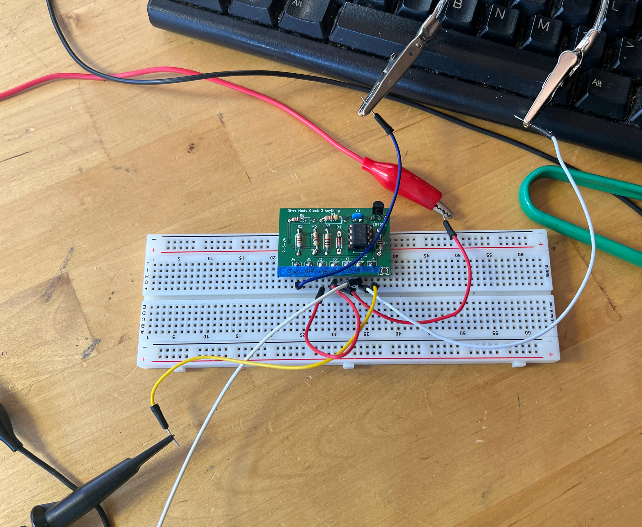 |
| With the correct resistor values: "seems working" |
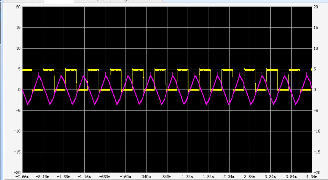
Elton's design worked great, nice clean square waves regardless of a sloppy signal at the LM311's inverting input.
The BoB featured a low parts count--and, if going forward I used an SOIC LM311 and SMD resistors, this design could get really small.
UPDATE: 7-27-24 I did another run of Ottermods' design, correcting silkscreen issues for pins J1-J7. This rev2 gerber can be found on the PCBWAY Community site. Many thanks to the folks at PCBWAY for helping me update and improve these community projects.

 |
| Updated board with improved silkscreen legends |
 |
| ramp to clock... |
 |
| random to clock... |
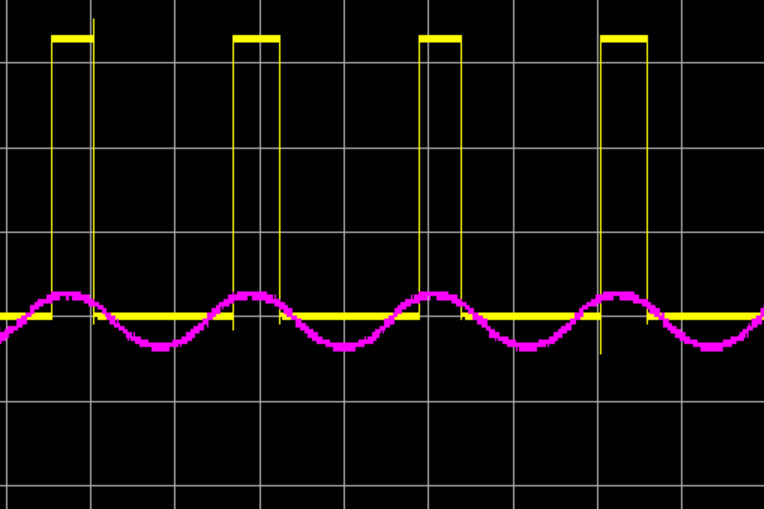 |
| Sine to Clock.... |
 |
| Tri to clock.... |
So what's next? I hope to use this BoB for input buffering and rising edge detection for a clock multiplier, perhaps based on an RP2040.
But! With my day job going full swing post-pandemic, will I have time? We will see.