Showing posts with label RP2040. Show all posts

Rotary Encoder Expermenter's Board: Improving the Hardware

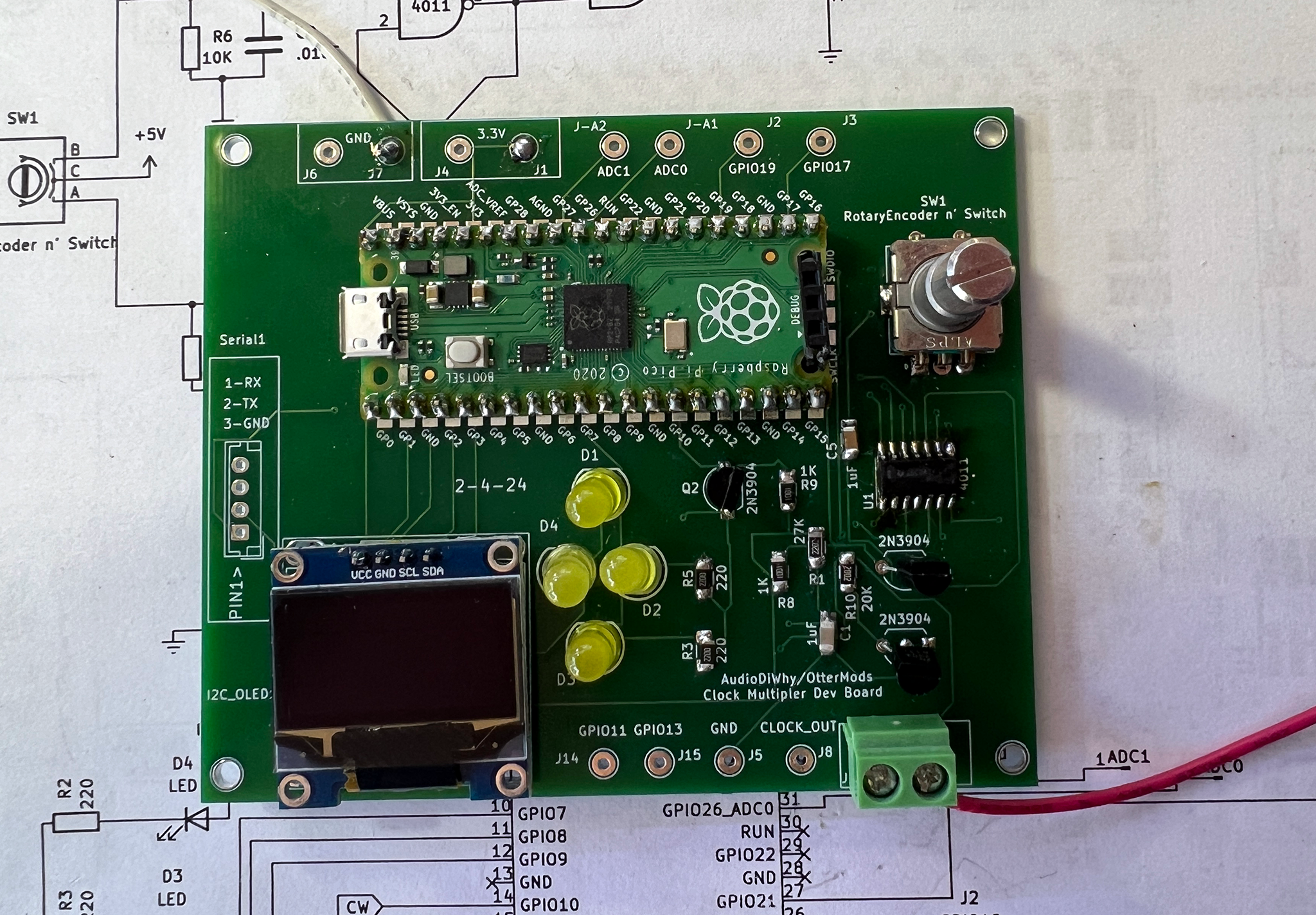
Quick one this time....I have posted a few projects lately that incorporated a Raspberry Pi Pico, rotary encoder, and .96" OLED: here, here, and here. To make it unnecessary to breadboard the hardware, I posted an "experimenters board"--a development board to augment a RP Pico that adds a rotary encoder, an OLED, and a buffered GPIO output, and other enhancements.

Just now I updated the KICAD and Gerber files on the PCBWAY community site salient to the posts: here.


The 9-29-24 revision of the experimenter's board uses less components, incorporates the encoder debounce library here, superseding the less responsive CD4011 based hardware debounce discussed here. 

Good news: it all works.

Thanks to Wendy and the gang and PCBWAY for patiently providing revised me with PCB's. You can help this blog by checking 'em out. 

9-29-24 revision

To make sure the grounding issues I saw with earlier revisions was a function the PCB's layout, not the schematic nor code, I breadboarded the entire "dev board for a dev board":


The breadboard example worked every time, but some of the older experimenters PCB's didn't, so, for versions of the board prior to 9-29-24, I was fairly certain this was a hardware/PCB layout issue.

I thought trace layouts for low frequency audio wasn't terribly important--put things almost anywhere, throw in whatever traces you want--it will work--we are bottom feeders?

Wrong. Apparently the I2C traces (at the very least) needed to be treated with forethought.

Previously: more narrow traces....no ground pour


9-29-24 design improves that. 

I found myself putting the 9-29-24 assembly on hold for a couple of weeks, partially because I was tired of revising the board, and also having a feeling (incorrect, fortunately) that the 9-29-24 revisions would make things less reliable, not more.


Word of caution: 1306 128x64 .96 OLED's are everywhere but there appear to be 2 different pinouts coming from Shenzen: GND far left, and VCC far left.  

My design requires VCC on the far left--make sure you get that style of OLED if you build this project.

Spinning the rotary encoder advances or diminishes the counter on the OLED as expected. Every time, without fail. Thank goodness.  

Next: I have augment the code to create a user interface for the frequency counter....yes, I will get to that someday, but it means a lot of code changes.  

For now it's back to my day job--for better or worse the global pandemic is over.

Debugging Raspberry Pi PICO with a Segger J-Link EDU Mini

In the previous post here I set up a $4 "Picoprobe" to debug RP2040 C/C++ code running on a PICO development board. 

This worked OK but I found it a bit unwieldy at times; the debugger was often physically larger than whatever I was debugging. 

Could I get a smaller debugger into play?

A tech friend told me about an inexpensive educational version of popular Segger J-LINK debuggers; I read online that Segger had made a "mini" version of it. 

Segger's J-LINK EDU MINI debugger. Yes, it's mini.


I emailed them; their sales team got back to me quickly. 

This is a USD $60 purchase for non-commercial use; even though it's for education ("EDU") you don't have to present a student ID. 

But you also can't make money off your code.....all my audioDiWHY code is MIT open source so I figured: I qualified.

The Segger page here made me think the adapter would work for debugging RP2040's. For what this debugger can do and all the Segger software it came with it seemed like a hell of a bargain. 

I bought one.

WIRING IT UP

It's tiny! Its JTAG/SWD interface uses 2x5 pin 50 mil pin headers--1.27mm --extremely small--conforming to the "Coresight 10" JTAG pin specification.

The unit comes with a 10 pin to 10 pin IDC ribbon which won't work with the PICO; the PICO has SWD pins that are 100mils apart. 

I had a JTAG 50 mil to dupont breakout I got with my Atmel Ice programmer; this breakout was unused, so I used it here; you will need something similar; try the link here.

OK, time to wire it up. I had to dig around on the Internet re: how to connect the EDU mini to a Pico Dev board and eventually figured it out:

 An SWD breakout is coming soon from this blog's helpful sponsor: PCBWAY.

I wired it up on a breadboard:


Unexpected:  "pro" Segger J-Links have a 5V output for powering your development board, but the EDU mini requires a 5V reference and cannot source 5V.

So: I used a bench 5V power supply for this.

It was time to check my wiring. On my windows system I installed the Segger tools (here) and ran their Commander utility  to verify all the wiring was sound--it was.

DEBUG SOFTWARE

From the previous RP2040 debugger post I knew I needed a version of GDB for the Segger J-link, since GDB can be to be hardware dependent; fortunately Segger's build of GDB for the J-Link was available as a free download: here.

OK, the next problem: how to set up the modified debug toolchain without going crazy?

After some research: I would continue to use Ubuntu VSCODE (as opposed to a different IDE) as the path of least resistance.

Note:The previous post on the initial Ubuntu/VSCODE toolchain setup is here. If you are setting up Segger/GDB/VSCODE for RP2040 "from scratch" you may want to read it or find advice elsewhere on the Internet.....you will need the same extensions for VSCODE installed for the Segger debugger to work as PicoProbe: C/C++ and Marus25's Cortex Debug, along with the arm-non-eabi compiler and so on.

I installed Segger's GDB code on Linux (I use an Ubuntu virtual machine) which ended up in /opt/SEGGER.

Now came the tricky part: getting VSCODE's dreaded launch.json file configured use Seggar's version of GDB.

Here is the launch.json I ended up using; this got copied into my project folder's hidden .vscode subdirectory after renaming the existing picoprobe launch.json file to launch.json.old.


####################

{

"version": "0.2.0",

    "showDevDebugOutput": "raw",

    "configurations": [

     {

        "name": "J-Link",

        "cwd": "${workspaceRoot}",

        //"gdbPath": "gdb-multiarch",

        "gdbPath" : "/usr/bin/arm-none-eabi-gdb",

        "executable": "${command:cmake.launchTargetPath}",

        "servertype": "jlink",

        "serverpath": "/opt/SEGGER/JLink/JLinkGDBServer",

        "armToolchainPath": "/usr/bin/",

        "request": "launch",

        "type": "cortex-debug",

        "interface": "swd",

        "serialNumber": "801056408", //yours won't be

        "device": "RP2040_M0_0",

        "svdFile": "${env:PICO_SDK_PATH}/src/rp2040/hardware_regs/rp2040.svd",

        "postRestartCommands": [

          "break main",

          "continue"

        ]

      }

    ]    

}

In VSCODE, on the bottom right, I had to set the file type for launch.json from "commented JSON" to
"plain text"....then throw away the previous build file and recompile my stupid blink main.c then push the .UF2 file to the Pico.

It worked! 

With this new debugger in play: I can see registry contents, set breakpoints, watch variables, all the usual debug stuff, without having to leave VSCODE. 

And--I got it to work in about 4 hours, start to finish, on single Sunday--surprising even myself. 

SIDENOTE: RTT ADD-IN--FAST PRINTF()

GDB is cool, but arguably nothing in the debug world is easier and cheatee-er than a C printf() statement to reveal a variable's value or whatever.

Come on, we all do it right?

Problem with printf(), the version in the RP2040 stdlib anyway: it's pretty MPU hungry and can jam up other I/O while sending strings to the terminal.

SEGGER provides a freely available, more efficient printf() algorithm that's easy to throw into your project. 

Here's how I set that up:

  • Downloaded the tools for debian from the "J-Link Software and Documentation Pack", here. 
  • Right clicked on the .deb file, said "use other software" and ran the .deb installer.
  • The files I needed got installed in /opt/SEGGER.
  • Gunzipped/unpacked the files in /opt/SEGGER/JLink_[version]/Samples/RTT;
  • I needed SEGGER_RTT.c, SEGGER_RTT.h, SEGGER_RTT_Conf.h, and SEGGER_RTT_printf.c....
  • I copied those files into my RP2040 project.

Next I modified CMakeLists.txt and .c files to get the RTT printf() statement to work. 

Please go to Github (here) and look at the example/proof of concept files, including an example CMakeLists.txt; I think you will find it pretty easy to get an RTT printf() statements into your projects once you see the examples....in the repo--main() is in the file blinkcl.c....

If you want to download and run the Proof of Concept, I called the project BLINKRTT; to make life easy, grab the UF2 file from the repo and upload it to your Pico dev board.

With the sample code loaded into a Raspberry Pi Pico:

  •  I hooked up the J-Link Debugger using the wiring diagram above.
  • Went back back to opt/SEGGER and opened JLinkRTTViewerExe:


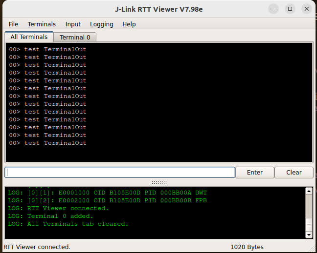
With the RTT viewer open I needed to connect the RP2040, so I went to to file > connect and clicked the three dots (...)


 and choose the RP2040 Core 0 from the drop down, finally, clicked OK.


When I powered up the PICO the RTT print statements showed up in the RTT viewer:


RTT has a bunch of other cool features--printf() is only a small part of what it can do--more information here.

OUTTRO

Overall this was a great addition to my bench tools. Getting the J-Link Mini going was much smoother sailing than other debug hardware + software setups to date. 

For $60 the Segger J-Link EU MINI is a heck of a deal, especially considering all the software that comes with it.

In future posts I will build/post a simple JTAG to SWD breakout board, which will hopefully make quick setup for the JLINK and other SWD debuggers. (Update--ha! done, works! go here) 

Until then: don't breathe the fumes.


Debouncing a Rotary Encoder Revisited

Update 9-29-24: Be warned, I have built a few of these boards now and some of them work and some don't. Not a fab issue, a design issue. I will revise the ground pours etc., I think this is a layout issue. 

UPDATE 11-2-24: new trace layout has fixed the issue!

 If you want to build the project featured in today's post anyway, please go to PCBWAY's Community pages--gerber file (main board) ready to download and/or fabricate, KiCAD pro/pcb/schem files and a BOM are here.  

You can also help out this site immensely by checking out PCBWAY using the link here. Thanks!

----------------------

Rotary encoder debouncing is alive and well: here, here and here for instance.

This post I try out an interesting debounce algorithm, silencing my rotary encoder's chattering teeth once and for all, using a small bespoke development board centered around the Raspberry Pi Pico and its RP2040 MCU.

Good news: this new (to me) debounce algorithm works great.  


This all started when DIY mensch Christer Janson emailed me, postulating a way to do encoder debounce using pin state as opposed to more the traditional methods: using hardware (example here) or waiting a few milliseconds after initial contact to let the chatter subside (here). 

I was baffled, his idea seemed too far out.

A few days later Christer emailed me again with a link to Marco Pinterec's website where this unusual  debounce paradigm is discussed. 

Ralph Bacon's video (here) shows Marco's idea in action.

"Sit on it and rotary"


To (over)simplify: the algo reads the encoder's state once pins have settled into a physically possible condition and only then outputs value indicating that the encoder is incrementing or decrementing.

Christer took the code from Marco's site and turned it into C++ classes. One class can be used when an interrupt is fired ("CCJISREncoder"), also a inherited class for polling encoder(s) using an infinite main()  loop ("CCJPollEncoder").  

Cool! 

Get the code from Christer's website here.

You can get my Raspberry Pi RP2040 port of the polling algo on Github, here; the ISR version with a main.c example is here.

GETTING IT TO WORK....

This was a simple one right?

Not at first. 

Before working on debouncing of any kind I strugged for 3+ evenings (!!) getting the Pico's serial TX pin 0 connected to an Ubuntu Linux PC running Minicom to display output. 

I have been using serial UART with Pico dev boards, SBC's, and ATMega328's since about 2019 without issue.
 
For this project I cracked open a batch of new PICOs; 4 boards total. 

I found that one new PICO could output a 112K serial stream for a few seconds before the stream stopped, while the other three didn't output serial at.  

Hello???? 

Of course I was using "hello snotrocket" code to test the output; I knew the code worked, having uploaded and tested it on earlier Picos without issue.

I tried everything--in the most logical manner I could--different computers, different USB ports, different GPIO pins, different USB cables, a CH340 based clone instead of an FTDI for serial to USB, all to isolate what worked and what didn't; no luck. 

It had to be the new batch of Picos!

Pico of crap? Usually not. But four from Amazon had a problem with breakfast carbs: i.e., serious cereal issues.


Adafruit's FTDI F(r)iend! converts RX/TX serial to USB.  Easy to use, well documented; works on Linux OS without extra drivers. Highly recommended, but only if the board you hook it has a working serial TX output, dammit.


After a lot of Internet research, scribbling notes, more Internet research, looking at scope output, reading many SDK pages, and still more Internet research, I guessed that I had some sort of pullup or pulldown issue, not needed in all my previous Pico dev boards, but somehow, for these four new ones, necessary.

Mind you, this was a guess.

I put a 10K resistor between TX and ground--still broken.  

But to my amazement: when I put the 10K from TX to ground--FIXED.  For all four!

Speculation: my older Picos had different component tolerances regarding output impedance, so they worked without the 10K pulldown, but this newest batch, nope--pull down resistors for TX were obviously needed.

Oddly, I couldn't find anyone else on the Internet with the same issue. 

Maybe most DiWHYers use the USB cable based Arduino terminal window instead of GPIO pins for serial, so, if it didn't work, well, no one cared.

Maybe I got a few lemons from Amazon and no one else did?   

I will never know. 

Anyway...I soldered a 10K resistor between TX and ground. I incorporated this mod into the gerber I uploaded to the PCBWAY community site. If you build this board and are using serial pin GPIO 0 (TX) for output, you might want to use a 10K 1206 resistor for R6.  

A potential solution and it ain't pretty.


I figured some sort of pulldown method in code could also be put to the test but that's for another time.

To get to the bottom of the pulldown issue I recreated the design (adding an OLED) on a breadboard; in this configuration, no pulldown resistors were needed.


THE CCJ ALGORITHM

Christer's code demonstrates his deep knowledge of C++, using protected classes, virtual functions, inheritance, and more.  

It was written for AVR/Arduino so I had to change things like "digitalRead()" to C SDK functions for the RP2040. 

How to use it?....if you are calling the algo from an infinite "while" loop there is not a lot more than this:

CCJPollEncoder encoder1; //instantiate


int main() {
    
   stdio_init_all(); //initialize printf
   encoder1.init(10,15); //initialize GPIO pins
 

//In a main{} infinite loop:

            if (encoder1.check())  // we call CCJ class method
            {
               int a = encoder1.value();     
               printf("Value is: %d \n",a);  // print out inc/dec                                                 //value via serial
            }

For Christer's "CCJPollEncoder" library I initialized two GPIO pins and ran two function calls; when check() returned a true, value() picked up an incremented or decremented value based on the rotary encoder's state. 

But, with serial I/O working again, could I make it go? 


At first I saw nothing, no serial data, no increment, no decrement, even when the PICO could stream "hello wheaties" all day long running other firmware.

I reached out to Christer for help. 

He reviewed my main.cpp file and suggested removing gratuitous LED flashes I put into main() since they might be clobbering the serial stream.
  
He emailed me this clever "only flash your LED when nothing else is going on" snippet to use instead:

//before main

uint64_t blinkTime = 300000;
bool ledState = 0;

//inside main()

absolute_time_t lastBlink = get_absolute_time();

while (2) {
        absolute_time_t curTime = get_absolute_time(); // current                                                             //time
        // Check time since last blink, if time since last blink is          //larger than blinkTime, then blink.
        if ((absolute_time_diff_us(lastBlink, curTime)) > blinkTime)
        {
            lastBlink = get_absolute_time(); // update blink time
            ledState = 1-ledState;                 // Flip ledState                                                     //between 0 and 1
            gpio_put(LED_PIN, ledState);    // update led

(Wow! This is cool. A million and one uses--Telling you: Christer has the skills to pay the bills.  ).

With Christer's improved LED flash mini-algorithm the CCJEncoder class worked immedately and worked great.  

I could see the rotary encoder's output increment (CW) and decrement (CCW).  

And best: the encoder debounce was--perfect.  

I mean Abso-frigging--lootly--perfect. Never a false positive. never an issue.  Never a missed beat. Perfect!!!

update 8-24-24: next I ported Christer's "ISR" class to RP2040; tested it working as well. If you want to use RP2040 GPIO interrupts to grab encoder data, vs. infinitely polling, you'll want this version--get the C++ .h file and example main.c at github: here.


"seems working"


BUILDING A DEV BOARD FOR YER PICO DEV BOARD

If you follow this blog you know I hate breadboarding, so I moved the project to a printed circuit board, adding functionality to the PICO, fabricated by my ever patient and supportive sponsor, PCBWAY.  

 
Shout out to PCBWAY for sponsoring this blog. If you have PCB, 3D printing, metalworking, you name it, needs, please check 'em out.


Populated--working!


OUTTRO


There is a long way to go with this one...I want to code a simple encoder driven user interface for the OLED for the ongoing RP2040 frequency reader project.  

All of this in the middle of busy times at my day job...but I will get it done right?

"burned up sir"

One more tidbit before going back to work...in the midst of my issues with unreliable serial ports I took no mercy on one of the 4 misbehaving boards.

I got out my rework station, melted the crap out of a PICO, then literally threw the tiny thing out the window.  

This didn't make me more productive, but it felt pretty good. 

I had a tech boss long ago who liked to say: "anything can be fixed". 

Sorry, not this time.

Frequency Counter using an RP2040

Readers: If you want to build the project featured in today's post, please go to PCBWAY's Community pages--a gerber file ready to download and/or fabricate as well as Kicad files and a BOM are here.  Firmware for the reader (work very much in progress but frequency reading the OLED display function) is here.

Also please visit PCBWAY's site--using the link here--it will help this blog immensely. Thanks.

====

I want to build a clock multiplier for my bench, but first I needed a way to accurately read frequencies of incoming signals. Between 10hz and 100K?  Sure. Good start.  

I got that working this morning:


For prototype hardware I used an already fabricated PCB I designed: post here.

This time, as with many times before: my patient and tolerant sponsor, PCBWAY, helped ameliorate my frustration with breadboarding....for $5 and shipping, I threw most all my error prone dupont jump cables into the dumpster.  

Then I coded  in C using more reliable hardware--a PCB:

When I breadboard, and it doesn't work, why not?  Is it a broken dupont cable? A wire put into the wrong 100 mil hole? A dumb design mistake? All of the above. The PCB I used this time is an encoder + GPIO  development board centered around a PICO dev board which in turn is centered on the RPI RP2040 MCU.  This saved time and anguish. Get this PCB here.


Unfortunately for this bench configuration not all the breadboards were gone! 

To buffer the incoming signal I tried out two different designs, "anything to clock", see posts here and here--each A2C version was on its own PCB which in turn was mounted on a breadboard. 

These small PCB's rectified incoming signals to turn them into rising and falling edges and clamped the output to 0-3.3V so as to not blow up the RP2040's GPIO inputs.  


The firmware for the reader is based on a cool RP2040 counting algo by Jeremy P. Bentham--see his blog post here and Github page here. 

I modified Mr. Bentham's code a little, but not much, and made it display observed frequencies on a small OLED display using David Schram's open source C library for SSD1306's: here. 

A few minor code changes were needed, for instance, the frequency reading algorithm put the frequency value into an integer in memory, but for the  Schram1306 library I needed a string.

Easy--there is a function in C to change ints to strings that I didn't know about--snprintf:

#include <stdio.h>

#include <stdlib.h>

char buffer[10];

int value = 234452;

snprintf(buffer, 10, "%d", value);

//buffer -- input string

//10  -- base for conversion

//%d   decimel output

//value   input number to convert to a string.

Another cool thing--the Bentham code traps the frequency and sends it out the RP2040's UART pins if you configure CMAKE to do so. Not sure what I'd use that serial stream for, but hey, it worked, and for the final build I will probably bring this data to the front panel on a TRS jack.

The ink on the firmware from the reader is still wet--there might be bugs? This is version  "less than point one", folks. 

But for me, JOY! it worked.

Get the code here.

WIRING

I add the wiring diagram below because in 3 days I will forget how I wired all the dev board on my bench and be extremely unhappy to have to figure it out again. Live and learn?  

Usually nope, this time--maybe:


The breadboard equivalent of the dev board. LED's and GPIOs currently not implemented in code are not shown.


Pico Pinout.....


Still to Do:

--I need another algorithm to analyze incoming low frequencies--say .5hz or .1hz to maybe 10hz. Not useful for audio, but in music synthesis, recording studios, bench automation and other environments I see these low frequency rising and falling edges--frequently. 

--Utilizes the second core of the RP2040--looks pretty easy, see the video here. I've been putting experimenting with this important feature; maybe next time?

--Auto-ranging--the counting algorithms should change based on the rough frequency seen at input. So far I can think of 3 different settings: .01hz to 10hz, about 10hz to 2K, and 2K and above. So some sort of ranging is needed but I will probably get lazy and put this on a switch which might be good enough.

And of course, once I have everything jumpered together on the bench I need to turn it into a working prototype. More to come, but this project is starting to feel like a nuisance to me. 

The gerber to PCB part is super easy, thanks to my sponsors.  My own dedication to finishing this one--not as much.

More coming up. Until then, enjoy the beginning of summer.


RP2040 Dev Board--More Encoding, Less Breadboarding

Readers: If you want to build the project featured in today's post, please go to PCBWAY's Community pages--a gerber ready to download and/or fabricate as well as KiCAD files and a BOM are here.  

Also please visit PCBWAY's site--using the link here--it will help this blog immensely. Thanks.

====

Pretty quick one this time. 

I had some back-of-the-napkin ideas for a clock multiplier. Instead of breadboarding I had PCBWAY make some development boards to accommodate an RP2040 MCU ("Raspberry Pi Pico"), an OLED display, a rotary encoder, and some GPIO pins. 

Less to go wrong!

Dev board for this post's project...

The dev board primarily uses 1206 surface mount components. 

My thinking: it was easier to swap SMD resistors and capacitors if I needed to change values compared to through hole. Less work and very little risk of damaging pads and traces.

However, changing and rerouting traces when working with really small parts was not as easy as my older through-hole designs. 

I am still puzzling through the best practices here but I know I didn't want this:

Something about breadboarding, with the dookie-duponts going all over, just drives me-----nuts!!!!! 

No more, please!

The dev board's "features" reused ideas from previous posts:

  • Rotary encoder with hardware debounce--post is here. After some experimentation, the values for C and R and .1uF and 100K seemed to work OK.  
  • OLED 1306 I2C--post about the 1306 embedded C library I will probably use for the multiplier's  UI is here.
  • UART output with buffering for handling printf() statements and serial input data. Got this idea from the fantastic YouTube Channel low level learning.  More information about this in the previous post here.
I wrote embedded C test code, that's on GitHub (here), which "seems working": turning the encoder produced "CW" and "CCW" on the display; clicking its switch cycled the 4 LED's.

The RC + CMOS 4011 based debounce worked most of the time, but not all of the time. This drove my crazy for a few evenings, thinking: where is the mistake?

I simulated a rotary encoder in Logisim (here) which informed me the existing debounce--the digital side anyway--should work.  

I looked over my code many times, no, I thought it right. 

I tend to always blame my own crappy work, bad assumptions, sure I'm right when I'm not, etc, but this time maybe it's something else?  

Perhaps the issue was with the encoder itself? The part says "ALPS" on it, which should be a quality encoder, but I bought 20 in bulk for something like 50c each from China.  

The real deal is more like $2.25US and up per unit.  

So my encoder might be a fakecoder, a counterfeit, which is why its performance, even after hardware debouncing, was not spot on. 

I will buy some name brand encoders from Digikey, not fakes, we will see what happens.

Anyway, I got building:

Happiness is new boards from this blog's sponsor PCBWAY


"Parts is parts"

Rev 2 board will have changes to the silkscreening, they always seem to, but otherwise, this dev board "seems working".  I have uploaded the revised board to PCBWay's community site, here. 

Power test. Good news--the 4011 did not fry.

For serial monitoring I used an "Adafruit FTDI Friend" adapter (here) to a Linux PC.


So what's next?  I have some open source algos I found to get the time between GPIO pulses (for instance: here and here. Beats writing the code from scratch!

Next step I figure: as easy (?) as averaging a few readings of  the incoming frequency, then multiplying that value by 10 let's say.   

Then, use PWM (using the  Pico SDK or maybe the library here) to output the 10x frequency. 

But is it ever that easy?  I am sure there foobars I have not thought of yet.

I am really short on time these days, but if I can find time to code this, as I say after an Olzempic pizza and beer chaser: I will let you know how it comes out.

RP2040--Simple C Library for SSD1306 displays

For upcoming projects I want to include SSD1306 based displays for RP2040 based audio projects. Easy in Micropython, but what should we use for Embedded C?  

No-name, super cheap I2C SSD1306 OLED display.
Gotta love the umlaut in "menu"!

I found a really good C library for this application. written by David Schramm, here. It gives us useful 1306 display functions without extra bloat.

This time: I get this library working on the bench: different strings showing up on the OLED based on the position of a rotary encoder.

I also get additional font.h files working with the library, from content found here.

Working on the bench....

Use your Library Card!


This is the same idea as the Atmel 328 SSD1306 C library described in this post, but with a different MCU. 

I could have written my own library for the 1306 OLED but didn't have time, so I used this library's abstrations instead. 

Documentation for this SSD1306 I2C C RP2040 library are here.

The development board chosen for testing was the Raspberry Pi Pico. 

Writing the code

First up was to get the example code working which was really easy. 

I downloaded the library and code examples here and loaded it into my usual toolset: Pico/Pico SDK and VSCODE, running on an Ubutu VM--posts for my RP2040 C toolchain begin here.

The library's provided test code compiled first time with no issues--impressive! I had this all up and running in about 15 minutes.  The example code showed some basic graphics and a few different fonts whizzing by on the OLED. 

So far, so good!

On to see if I could get a rotary encoder to display "CW" and "CCW" as the encoder was rotated, well, clockwise and counter-clockwise ("anti-clockwise" in the UK, which is a much better phrase).

I had trouble with this, and it was my own fault.  

Here we go....

Encoders and Hardware


I bought a bag of surplus top-shelf ALPS encoders that had incorrect documentation. These were high quality encoders at a ridiculously inexpensive alibaba price--but as I say so often--what is my time worth really? 

Turns out its pins were wired up the same as every other 3 pin encoder I have ever seen.  The included photocopied documentation was just plain wrong. 

Doh!
High quality, surplus encoders. Usually cost $3.25USD or so each, I paid something like .25c USD each. How could I fail?


Sketchy Xeroxed documentation that came with the surplus ALPS parts (no designation of which ALPS encoder was on the part) had the ground on the leftmost pin--nope. Above is the correct wiring and conforms to most encoders out there. ARRRG!!! No, I can't show you a scan of the incorrect documentation, because I lit a match and burned it.


Wiring used to test the OLED from a rotary encoder. For power: connect 3.3V bench power to pin 39/VSYS ("-2" on some RP2040 pin diagrams); bench GND to RP2040 38/"-3"; 1306 Vcc pin to regulated 3.3V power on RP2040 (36/"-5"). PICO Pin1 is TX; hook it to RX on your serial reader.


Breadboard test setup

Next it's on to this post's stupid coding mistakes. 

It had to do with how I was reading the encoder. 

But first, I need a few minutes to talk about how the encoder was being read by my test code....

A line of code in main.c's infinite loop sensed if the encoder state had changed at all; then, saw if A and B were the same or different. If they were the same, the encoder was turning one way, if different, the other. Read more here, this is a pretty standard "read the encoder" algorithm. Easy, right? 

Not for me. I used the UART based reboot code found in a previous post (here), but the UART reboot code has a scanf()which made the loop break. Until this was commented out, the encoder didn't work at all.  

Time wasted: twenty minutes?

However it was the next dumb mistake that cost me an entire weekend day.  

I put a sleep_ms(200) into the main loop. The idea was to...well I am not sure really why I put that in there!  This made the encoder's outputs almost always read "both 1s or "both 0's"....so, the sleep statement broke things. After sleeping the main.c woke up and queried the rotaty encoder to see if the encoder state had changed but it was--too late!! I had to catch the encoder's lows and highs right when they change...which means the main.c loop had to always run unimpeded. 

Took me a while to find the errant single line of code and get rid of it.

I will go into more detail about encoders and RP2040 in a future post. The encoder read really should to be done with interrupts, not a loop. But not now--fixed--onward.

OK, with the encoder sorted, it was time to move on to the OLED itself.  

CHANGING AND MANAGING FONTS


There is a string function in the library that allows you to argue in the font you want to use--cool!  

ssd1306_draw_string_with_font(&disp, 8, 24, 2, fonts[2], str1);

And the sample library provides 4 fonts, but 3 of them weren't that useful to me, more designed to show off some of the odd characters you can display on a 1306 vs. things I would use in a project.

Good news, you can get more fonts for the library, using content found here. 

Even better, the fonts repo has PNG files that show how the fonts will look on the OLED once compiled. Very cool!

You have to edit the .h files a bit to make them work with the library--not too hard--here are my bench notes describing how to edit them:


/* how to use font.h included here 
See  https://jared.geek.nz/2014/jan/custom-fonts-for-microcontrollers#drawing-fonts

--#include the font in main.c

#include "fivexfive_font.h" //name of edited font file

--call the font in main.c (add it to fonts array 

so add the font file (without the .h!) at the end of this array in main.c
const uint8_t *fonts[6]= {acme_font, bubblesstandard_font, crackers_font, BMSPA_font, renew_font,fivebyfive_font};)

then call it: fonts[5]   eg:

ssd1306_draw_string_with_font(&disp, 8, 24, 2, fonts[5], str1);

You also have to modify the .h font files to work at all, or else the imported font files won't compile.

In general, Use existing [font.h] files included with the 1306 library as an example of how to format the new .h files:

in the font.h file get rid this line:

const unsigned char font[96][6] 

and use this instead

const unsigned char fivebyfive[ ] = {

where fivebyfive is the name of the font file without the .h extension, elmo!

for the first row use this

8, 7, 0, 32, 126,

where 7 is the number of columns in the array (usually 6 or 7) and the 0 is extra # of spaces you want between letters.

Get rid of the extra curlies in the guts of the array data,i.e., all the rows with 0x00, 0x70, 0x00,0x00, 0x70, 0x00 but leave a single curly at the beginning and a curly and ; end of each font
.h "how will the letter look?" data. 

save everything and compile

Test it.


*/

Ha!  I edited 2 of the font.h files for the library.  They are included in the github repo that captures the test code for this post. And they work....

DEBOUNCING THE ENCODER

It became obvious quickly that some better debouncing of the encoder was needed. The CW and CCW track some of the time, but not all the time..

I found an interesting "software filter" idea (for Arduino--but should work for any MCU) here.  

My adaptation of this:

static uint16_t stateA=0,counter=0;

 stateA=(stateA<<1) | gpio_get(ENC_A) | 0xe000;
 if (stateA==0xf000)
{

//trap encoder stuff here.
}

StateA  fills up LSB to MSB; then we see if the LSB values are jumping around.  

If so, don't do anything. Once it's stablized, proceed.

I have had mixed results with this code addition. An RC filter is still needed to get rid of chatter and only slower turns of the encoder are seen. I continue to bounce around.
 

OUTTRO


In case you missed it--you can get the code I used in this post from github, here.

And/Or--get a simulation in Wiwok: here.   

Victory!

With this set, the "CW" and "CCW" strings look good in various fonts. I still had some encoder issues however as I describe above. Most of the time the correct string is shown on the OLED, I figure when it displays incorrect data it is because better debouncing for the encoder is needed.  

Again I will dig into encoders and encoder debouncing in greater detail in a future post. 

Until then, code well and live!