Sunday, May 29, 2022

RPPICO/RP2040 Toolchain Part II: Debugging RP2040 projects using a "PicoProbe" and Ubuntu 20.04

This time I continue to set up a toolchain for the RP2040 for Ubuntu Linux 20.04 running as a virtual machine.  To follow along, you'll first need to set up the basics--or at least skim the last post--here.

Hello again! There are about 8 billion people in the world; am I the only one who wants to set up a debugger for the RP2040 MCU--what the Raspberry Pi Foundation calls "PicoProbe"--centered around an Ubuntu 20.04 LTS virtual machine?

And code in C, not MicroPython?

Um....Perhaps?

Picture this: a debugger interface as big as a box of matches. Works from Linux command line as well as VSCODE. We can put the incredible horsepower of GDB--a well known open source C/C++ debugger--to debug an ARM MCU....the RP2040....all for $4USD?....unbelievable!!!! 

If I can get it to work.

WTPP (or) Rasberry Pi in yo Face

PicoProbe uses an intermediate Raspberry Pi PICO dev board to provide SWD debugging to our target RP2040; we also need a computer to run GDB.  

It's not simple.  

I found generic Linux debugger toolchain installation steps from Raspberry Pi and elsewhere, but quickly discovered they didn't apply and/or were out of date for Ubuntu Linux 20.04.  And, almost every Linux based build I found used a Raspberry Pi SBC as the host Debian based PC, e.g., here, as opposed to an Ubuntu virtual machine.

Sure I could set the step debugger up on a Raspberry Pi SBC, but they are very hard to buy right now, being out of stock everywhere. And to paraphrase the great John F. Kennedywe do [Embedded C toolchain setups on Ubuntu] not because they are easy, but because they are hard.  

I created a simple PCB to simplify patching between a PicoProbe SWD Debugger (left) and the RP2040 Pico target (right). I'll go over this PCB in this post.

Let's go!! 

I found two thorough videos for setting up a PicoProbe toolchain on Windows: here and here, and a good document outlining the same idea here

To understand how the toolchain (PC > PICO running a "PicoProbe UF2 > target RP2040) works, please watch the beginning (at least) of the excellent video from Shawn Hymel, here.  I am not going to outline each piece of the computer > Picoprobe > PICO debug toolchain puzzle in this post, because Shawn does an excellent job explaining them in his video. 

Me? I followed the RPI PICO Getting Started Document, page 58, and installed these packages on the Ubuntu 20.04 VM:

#sudo apt install automake autoconf build-essential texinfo libtool libftdi-dev libusb-1.0-0-dev

Next I followed the instructions on page 57 of Getting Started to set up a special pico version of OpenOCD, the service that allows the GDB debugger to talk to the Pico.

#git clone https://github.com/raspberrypi/openocd.git --branch picoprobe --depth=1 --no-single-branch

#cd openocd

#./bootstrap

#./configure --enable-picoprobe 

#make -j4

Here I found my first serious bump.  OpenOCD wouldn't compile--error 2 during the make command. The error was an indent bug (?) deep in the guts of the downloaded openocd.git code. 

No way I had time to rewrite the customized openocd source code so it'd compile on Ubuntu, that would have taken forever. Crap!  

After digging into the branches of the github repo, I guessed that the git clone command provided by RPi was out of date; I figured the repo changed and the official documentation didn't keep up. 

With fingers crossed I issued this command:

#make clean

then this:

git clone https://github.com/raspberrypi/openocd.git

cd openocd

./bootstrap

./configure --enable-picoprobe 

make -j4

sudo make install

Ha! It compiled!  I was right I think; the repo had been updated, but not the documentation. Time wasted: maybe 45 minutes.

Next I created a UF2 file for the Picoprobe.  This was straightforward, I used the toolchain I set up in last time and ran this:

(cd to your projects folder)

#git clone https://github.com/raspberrypi/picoprobe.git

#mkdir build

#cd build

#cmake ..

#make

No issues here. 

I uploaded the PicoProbe UF2 file to the Raspberry Pi Pico dev board I was going to use as the "go between". You can see how to do that here

"hold down the BOOTSEL button while plugging the board into USB. The uf2 file below should then be copied to the USB mass storage device that appears."
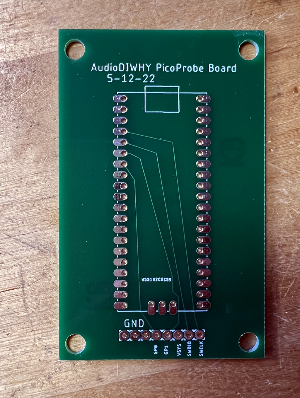
PICOPROBE PCB

I could have wired up this second PICO running the PicoProbe UF2 on another breadboard, but instead I got help from my faithful sponsors, designed a super simple PCB, and uploaded it to PCBWAY for quick fabrication. 

Back it came:

Boards arrived super fast from my generous sponsors PCBWAY.  Please help out a blogger (me) who is trying to teach himself electrical engineering in his spare time and check 'em out.


 I put edge connectors into a Pico Dev board and soldered it to the PCB:


bottom view....


Next I wired the new Pico Probe PCB (left) to the blink board from last time using dupont type M/M cables:

(The board on the right is running the Boring Blink Sketch from last time.....)


For wiring I matched the females on the probe board (left) to a Pico dev board (right).  The PCB has the names of the pins to connect to the target--so, wire SWCLK legend on the PicoProbe PCB to the SWCLK Pin on the target breadboard, the GP0 pin on the PicoProbe PCB to GP0 on the target, and so on.  

The LED on the PICO board went solid--and the target BLINKCL PICO still binked--still alive! The PCB worked. I put the PicoProbe PCB on PCBWAY's projects page; if you want to get one, go here.

Next I needed to get OpenOCD configured. In this use case, OpenOCD allows the computer to "talk to" GDB.

But did openOCD start up? Not at first. I started up a new terminal on my Ubuntu system, but the bash  code on page 60 of getting started didn't start openOCD on Ubuntu correctly and kept throwing errors. 

Fiddlesticks!!!!

After messing around with different command line variations, I eventually go this to work:

#sudo ./openocd -s ../tcl  -f ../tcl/interface/picoprobe.cfg -f target/rp2040.cfg 

And could see this from the Ubuntu terminal:

Open On-Chip Debugger 0.11.0-g610f137d2 (2022-05-28-16:27)

Licensed under GNU GPL v2

For bug reports, read

http://openocd.org/doc/doxygen/bugs.html

Info : only one transport option; autoselect 'swd'

adapter speed: 5000 kHz

Info : Hardware thread awareness created

Info : Hardware thread awareness created

Info : RP2040 Flash Bank Command

Info : Listening on port 6666 for tcl connections

Info : Listening on port 4444 for telnet connections

Info : clock speed 5000 kHz

Info : SWD DPIDR 0x0bc12477

Info : SWD DLPIDR 0x00000001

Info : SWD DPIDR 0x0bc12477

Info : SWD DLPIDR 0x10000001

Info : rp2040.core0: hardware has 4 breakpoints, 2 watchpoints

Info : rp2040.core1: hardware has 4 breakpoints, 2 watchpoints

Info : starting gdb server for rp2040.core0 on 3333

Info : Listening on port 3333 for gdb connections

So--what was in the Linux docs section from the official documentation didn't work on Ubuntu and had to be slightly modified. What do you want for free?  Time wasted: about 20 minutes.

Next I had to get GDB going in a second terminal. That should have been easy, but there was a (big) hitch--this wasn't Linux GDB I needed; rather, a special version of GDB for ARM processors, and arm gbd does not come with the gcc-arm-none-eabi package for Ubuntu. 

A baby's ARM, holding an apple? 

Damn! 

After doing some research, I found the stack exchange post here, which I used to solve the problem:

Install lib n' curses:
#sudo apt install libncurses5

Then, from a browser, I went to this URL and downloaded the x86/64 version of the ARM dev tools: 


Next I created a brand spanking new directory for the GDB executable:

#cd /usr
#sudo mkdir gdb  #creating new folder: /usr/gdb

I figured all I needed was GDB, the rest of the arm-none-eabi already worked, and assumed (!!) this newer ARM GDB version could coexist with the arm-none-eabi-gcc compiler I was already using, as long as the compiler was older than GDB.

This was a guess, but I had observed GDB used for other non-embedded projects to be pretty forgiving....

I unpacked all the gcc-arm-none-eabi files into the new directory:

#sudo tar xjf ~/Downloads/gcc-arm-none-eabi-10.3-2021.10-x86_64-linux.tar.bz2 -C /usr/gdb

Finally I simlink'd gdb, to fool the RP tools to thinking it was in /usr/bin:

#sudo ln -s /usr/gdb/gcc-arm-none-eabi-10.3-2021.10/bin/arm-none-eabi-gdb /usr/bin/arm-none-eabi-gdb

Did I have all the tools we need?  I ran the next four commands--yes--I didn't record the results, but the tools I needed were now in place.

arm-none-eabi-gcc --version

arm-none-eabi-g++ --version

arm-none-eabi-gdb --version

arm-none-eabi-size --version

Next I ran gdb (finally!) vs. the BLINKCL elf file from last time:

#arm-none-eabi-gdb BLINKCL.elf  

and got this at stdout: 

target remote localhost:3333

(gdb)

OMG!  The beloved (gdb) prompt!  Was this going to work????

(gdb) load   

 rp2040 running BLINKCL stopped blinking

(gdb) monitor reset init

(gdb) continue 

the rp2040 started blinking!!!

and we see the (gdp) prompt again!  

It worked!!!!  I could now use command line gdb to debug, same as if I was debugging C code on Linux!!!

BONG HIT VICTORY!

But wait--we're not done! 

Could I get debugging to work without leaving VSCODE? The video here and accompanying webpage here made this look--doable.

I followed this Shawn Hymel webpage and followed the section on installing the Cortex Debug plugin on.  It all seemed to be OK, including coding the settings.json and launch.json scripts.

However, when i tried to use Cortex/VSCODE to debug the blink elf file I got this:


Great, there was some sort of log to review, but where was this gdb-server's output?  

I wasted at least two hours throwing every bit of GDB kung fu I knew at this....do we enable logging?  Does log.txt show up somewhere? 

It should right?  However, there was frighteningly little information I could find online. Again, there are 8 billion of us, but I may very well be the only person trying to set up this exact version of the toolchain. Damn.

After many frustrating hours on this, I decided to watch videos about STM32 VSCODE toolchains, since I remembered that some of them used the same VSCODE Cortex Debug plug in. There was zilch about RP2040 and this error, but maybe it occurs for other MCUs?

Bingo! That did the trick, STM32's VSCODE toolchains indeed can throw the same error, and I saw a video that revealed the output for GDB was in VSCODE's terminal--click on the TERMINAL tab then on the right, the gdb-server link--my lord, how did I miss this???


From here--now that I could read the logs--it was obvious that it was a Linux rights issue for the USB port for the PicoProbe. 

I had seen this issue before; to fix it I ran this from the Ubuntu VM:

#sudo lsusb

Which showed me:

Bus 002 Device 005: ID 2e8a:0004 Raspberry Pi Picoprobe

I chmod'd that....

sudo chmod 666 /dev/bus/002/005

 After, the VSCODE debugger worked! Time wasted--oh, never mind.

BONG HIT VICTORY--MACH II! it's done!  I can next/step/continue/print etc. with VSCODE. 

That was fun--man, much harder and more time consuming that I expected. 

But: for $4, for this amazing code and functionality, that developers, RPi, etc. etc., must have put hundreds or thousands of hours into, well, I can't complain, so I won't.....but, this setup kinda sucked.

USING THE DEBUGGER

There are lots of videos about using gdb to debug C. (here for instance--"Low Level Learning" has a lot of great content).  

Lots of posts too; use the usual web searches. 

There are less videos about debugging using Cortex/VSCODE for RP2040, but there are several for using it to debug STM32's (e.g., here).  

And remember: after a debug, you still have to copy your repaired/modified UF2 file to the dev board--the debugger won't do that for you.

As usual: I'm not completely done, I'd still like to get a disassembler working, and I found some promising python code online, but I need to experiment with it further....one of these days. Until then, don't debug the fumes.


Friday, May 13, 2022

RP2040/Raspberry Pi Pico Toolchain--Ubuntu, CMAKE, and the Usual Boring Blink Test

 Hello again. I am fully recovered from Covid. It's time to keep marching forward.  

After finishing several projects based on Atmel's 328P MCU (a 328P based complex LFO is here, for instance), it was time to move to a new MCU family--something faster and more powerful. 

Contenders for this next evolutionary step in my AudioDiWHY journey were ST Systems' STM32 MCU's and development  boards--there are a lot of them--and Espressif's ESP32. 


Instead I chose Raspberry Pi's RP2040, the processor found in their PICO development board--mostly because the RP2040 was in stock pretty much everywhere I looked and is extremely affordable.


I chose RP2040 because it's the underdog?
                                    

TOOLCHAIN TIME

Here's how I got an RP2040 C/C++ toolchain up and running on Ubuntu 20.04 Linux.

I targeted the Raspberry Pi Pico development board.  It's inexpensive and well documented, and a toolchain that works with the Pico should work with whatever other RP2040-based PCB's I use for future projects. 

For this toolchain I needed software and hardware to write and debug RP2040 firmware (I code in C, mostly), compile the code, and upload the firmware onto the RP2040.  

I recently set up an Ubuntu 20.04 virtual machine running on VMWARE Workstation Pro 16 on a Windows 10 NUC computer (post about my bench setup is here).  I decided to go with this Ubuntu Linux VM for developing on the Pico--I don't use Linux as much at my day job as I'd like, so I'll use it here. 

There are many videos and posts about setting up a Linux RP2040 toolchain. The Shawn Hymel YouTube series here proved useful, as were the posts here and here; and the official PDF here. Also, The PDF for the RP2040 SDK is here.  

My Ubuntu build was "desktop"--that was my starting point....

First I sudo apt-install'd the software I thought I needed:

(from my home directory….)

mkdir pico

cd pico

sudo apt install git  #installs git

git clone -b master https://github.com/raspberrypi/pico-sdk.git

cd pico-sdk

git submodule update --init

sudo apt upgrade

sudo apt install gcc-arm-none-eabi

sudo apt install libstdc++-arm-none-eabi-newlib

sudo apt install build-essential     

sudo apt  install cmake  # version 3.18.4-2ubuntu1 

Can we use RPi's WGET?

To install a RP2040 toolchain on a Raspberry Pi, the RP Foundation provides a wget statement to build the entire toolchain with minimal end user interaction. It's here--go to page 4. 

We are not using a Raspberry Pi, rather Ubuntu, which is very close, so this "gee whiz it's easy!" single script approach might have worked. Or would it?

A common Linux trick is to remove the wget from the command, copy the rest of it into your browser, and see what happens.  

Here it the resulting URL:

https://raw.githubusercontent.com/raspberrypi/pico-setup/master/pico_setup.sh

Following this URL I saw a shell script....fascinating....and begs the question: who is Liam? regardless, I chased down how the script worked and decided it would be safer to build the Ubuntu part of the toolchain "by hand".  

Back to it: To get the system to locate the SDK files for RP2040, I needed to add this via the command line to the Ubuntu PC:

echo 'export PICO_SDK_PATH=$HOME/pico/pico-sdk' | sudo tee -a /etc/profile.d/pico-sdk.sh

To make that command take effect, I rebooted my Linux virtual machine, but I could have run this additional command:

source /etc/profile

With all this in place, I could compile the example sketches found in ~/pico/examples, build from the command line, drag the UF2 file to the PICO, and--we have BLINK! 

We are headed in the right direction. 

OK--next question: what IDE to use? 

I could write the C code using something like VIM (or Pico--different PICO....) but what fun would that be? 

I chose Visual Studio Code, the free (!!) multiplatform, multilanguage IDE from my bestest, smartest, most capitalistic buddies at Microsoft....a kinder gentler Microsoft, the one that no longer misses its meds--is Microsoft finally turning swords into plowshares? 

Nope.

Here are the commands I used install and configure VSCODE, I got these from this webpage.

sudo apt install code #install vscode for Ubuntu

code –install-extension marus25.cortex-debug

code –install-extension ms-vscode.cmake-tools

code –install-extension ms-vscode.cpptools

OK, one of the plug-ins needed for VSCode is CMAKE ("cmake-tools").  What is that?

ENTER CMAKE

It's a high level language--yes! an entire scripting language of its own--used to create Makefiles and perform essential software building/compiling automation.  CMAKE's webpage is here. Think autotools on steriods.

But--I got frustrated quickly with CMAKE. 

Most CMAKE videos and webpages were either geared toward total newbies like me and only discussed basics, like creating a Makefile for a single "hello world.c" file, or were extremely, and I mean extremely, complicated.

For software development shops, needing to compile, test and deploy complex software, CMAKE can do everything--however, CMAKE might be overkill for DIY folks trying to blink LEDs?  

In my case CMAKE kept throwing errors. It couldn't find the Pico SDK.  This should be easy!

I wasted over 3 hours trying to get this to work. 

To get to the bottom of this frustrating issue, I ended up buying a CMAKE book on Amazon (the book I got is the one here). 

With that in hand, I figured out the issue (see the "export source" statement above, that alone shoul have worked, but didn't, and the export $PATH statement provided by RP foundation didn't work for me--nor did tweaking path variables in VSCODE).

I am still not sure what caused the issue, or what fixed it, exactly--this should have been a really easy fix; it's just an export statement, but for some reason it wouldn't work for a very long time, then started working for reasons unknown.

Whatever--there is a whole career scripting CMAKE, right?  To learn more, the original CMAKE guy talks about his whole enchilada, here

Monkey CMAKE, Monkey C-DO 

CMAKE requires a single script in the project's root to work--called CMakeLists.txt.  No, you can't rename this file. No, you can't move it to some other folder. 

Here is the CMakeLists.txt I got to work for a blinkcl.c test program, which, well, blinks a damn LED. 

######

cmake_minimum_required(VERSION 3.13)

#include the cmake build functions from pico SDK

include(pico_sdk_import.cmake)

#project name and code here

project(BLINKCL C CXX ASM)

set(CMAKE_C_STANDARD 11)

set(CMAKE_CXX_STANDARD 17)

#bring in this function to add cmake Pico SDK functionality to build

pico_sdk_init()

#list out files used

add_executable(${PROJECT_NAME}

blinkcl.c add.c

)

#create extra uf2 etc files to copy to PICO via USB

pico_add_extra_outputs(${PROJECT_NAME})

#linker needs to use these libraries

target_link_libraries(${PROJECT_NAME} 

    pico_stdlib

)

###################

You may want to change the project name ("BLINKCL") and filenames ("blinkcl.c", "add.c") if you want to use the CMakeLists.txt files below as a basis for your own projects. 

And! One more thing--you don't need to list out .h files in CMakeLists.txt if they are in the same directory as your .c files.  

 I also copied the pico_sdk_import.cmake file into the root directory of my project ("BLINKCL").  This appears to be an include file (not sure that is the right term) that helps CMAKE find the Pico SDK.

For uploading files to the RP2040, I put the pico downstream from a USB hub with a power switch--you copy firmware onto a PICO by copying a UF2 formatted file from Ubuntu to the PICO, but copying these over requires holding down a button on the PICO while plugging in the USB cable.   

The switch on the USB hub makes that process much easier: hold down the white button on the PICO and flip the switch on the hub....


Blink me up, Scotty? 

My goal was to have 2 .c files, one .h file and everything else needed to build a multifile blink project.  

Here's the code:

#################################

#blinkcl.c

#include "pico/stdlib.h"

#include "add.h"

int main() {


    uint16_t time;

    time = add2nums(100,100);

    const uint LED_PIN = PICO_DEFAULT_LED_PIN;

    gpio_init(LED_PIN);

    gpio_set_dir(LED_PIN, GPIO_OUT);

    while (true) {

        gpio_put(LED_PIN, 1);

        sleep_ms(time);

        gpio_put(LED_PIN, 0);

        sleep_ms(100);

    }


}

#############################

#add.c

#include "add.h"


uint16_t add2nums(uint16_t a, uint16_t b) {

   uint16_t x = (a + b);

   return x;

}

#############################
#add.h

#ifndef ADDCH
#define ADDCH

#include <stdint.h>
uint16_t add2nums(uint16_t a, uint16_t b);

#endif

#############################

I built the firmware from these files without having to leave VSCODE.  

Yes the add.h file, the add2nums function, etc. are not needed, but I wanted to make sure the toolchain could deal with multiple .h and .c files. Yes, it could.

A tip, mentioned everywhere online when CMAKE is being discussed: if I altered my CMakeLists.txt file, I had to delete the entire build directory in my BLINKCL project folder then build the software again. Yes, I saw this, over and over.  

Last thing I did was get USB serial working for simple debugging.  I wanted to know the value of variable x?  

printf("x is: %d",x); 

This is very basic debugging.  

It turned out to be pretty easy.  I had to add this to the bottom of the CMakeLists.txt, rename the project, and rename .c files used:

#control USB output--1 means on.

pico_enable_stdio_usb(${PROJECT_NAME} 1)

pico_enable_stdio_uart(${PROJECT_NAME} 0)

Then I used this bash script from terminal to get minicom going.  

#!/bin/bash 

sudo minicom -b 115200 -o -D /dev/ttyACM0

I then wrote a simple hello.c project to printf "hello" 1000 times. It's very similar to the Pico example for "hello world".  I am omitting the actual code I used for this last test, but if anyone is interested, comment below, I can provide it.

I built it, and copied the UF2 file to the Pico.

The ascii output went out of the PICO, into the VM, and showed up in Minicom on the Ubuntu VM.

Joy!

Serial Ports--RP2 as a removable device on an Ubuntu VM--Why don't they work consistently?

As mentioned, my toolchain uses an Ubuntu virtual machine running on a Windows 10 PC.  The hypervisor for virtualization is VMware Workstation Pro 16.  A feature that caught my eye is what VMWare calls "USB passthrough"; I figured I'd need that since the RP2040 toolchain relies on the ubuntu VM reaching the Dev board via USB.

However, I quickly found that USB passthrough didn't always--pass through.

I had issues after the initial setup--the USB port used by the Pico/RP2040 was occasionally invisible to the Virtual Machine. Less frequently I lost the ability to see the pico dev board as a storage device, so i couldn't drag UF2 files to it.

Best I could tell this was because the PICO device was recognized as a plug and play serial device by Windows 10, which disallowed the device to be visible on the Virtual machine. So--in spite of my attempts to have USB "pass through" the W10 host, it--didn't.

Of course I messed with various settings as per the page here. No help.

To fix this, first I powered down the Ubuntu virtual machine.

Next, I went to device manager in Windows, checked "showed hidden devices", right clicked on the PICO device under "serial ports", left clicked on "uninstalled device" (I didn't uninstall drivers, just the device)

I then unplugged and plugged in the PICO to Windows 10 USB cable. 

The first time the PICO came back, and was visible again via Device Manager. Again this robbed it from being visible to the VM! But after doing this procedure twice, it appeared to be gone again.

After that, powering up the VM, I could see /dev/ttyACM0, drop UF2 files on the PICO, and so on. I was back in business.

Update: the problem is back. 

I blew away hours and hours today trying to understand how this works, so i could hope to get a final fix, but had little success. After several hours it started working again...not sure why.

What I think:

To make the serial transmissions "work as a USB storage device" on Windows 10, you really can just plug 'em in. I tried it on a W10 laptop--yes, it is plug and play.

However, to make the same features work on an Ubuntu VM, I had to get rid of all traces of "the RP2040 dev board talking to Windows". I used Windows device manager for this. I right click and uninstalled anything that looked Pico-ish: "RP2", "RP2 boot", "Pico", "PicoProbe" and so on.  

Once again this fixed it--for now.

As a baseline, here's a look at Windows 10 device manager when a Pico Dev Board is working as a storage device and "pass through" is working:


And here is it when it's actively sending serial data over USB (so, a correctly crafted printf statement, a correct CMakeLists.txt file; a successfully uploaded UF2 file)--the enabled USB serial device "moves up one":


The correct driver for these "VMware USB Devices"--and the only one that seems to work--is this one. 


A reboot of the Windows 10 host was needed when changing drivers....

Because the PICO could mount on the Windows machine or VM, it queried me to ask my choice--on which which device do I want the USB to be visible? I was tempted to say "always mount the Pico on the Ubuntu VM" when asked, but after wasting hours trying to get to the bottom of this issue, I changed my mind. Let it ask me each time.

Have I seen the last of this? I figure not. Until i know more about why this keeps breaking, it will keep breaking. 

Frustrating! There is a real lack of information online about how any of this really works--at a deep level--mostly I can find: forW10 just plug it in--it works; the drivers are included; and for vmware workstation pro--just plug it in--it works--the drivers are included. Uh huh. By magic, right?

Some basic considerations before I shelve this for now:
  • The serial port won't work (and minicom will close immediately) if there is no UF2 file loaded on the dev board.
  • Same if the printf or whatever is generating serial data is incorrectly crafted in code--just because it compiles doesn't mean it will work.
Update 6-22-22.  More digging into this--still having issues, especially with serial data over USB-- being able to see RP2040 USB serial content on the Ubuntu VM is still not working reliably.

 By using various tools perhaps I see what's going on here:
  • I upload a USB serial UF2 on the RP2040 dev board--it has a printf() statement for instance. 
  • this sends "hello world" or whatever out the USB port for a computer to display via a terminal program.
  • The Windows machine sees new USB serial traffic
  • An interrupt is sent to the Windows OS (?? How does this really work? I paid for a support ticket at VMware, to have them explain--but the tech seemed unwilling or unable do that beyond pointing me to the documents I've already linked in this post. If I get time, I may dig into this more and try to reverse engineer vmware "USB passthrough" technology, to better understand it, beyond the dreaded "plug it in and it just works" excuse) 
  • I choose "USB needs to appear on the VM" from the VMware USB passthrough UI.
  • Windows puts a VMware USB driver on the newly found port (?), giving up control of it.
  • ttyASM0 is created on Ubuntu, hopefully.  This is the /dev file created when Ubuntu sees a CDC USB device, which apparently is what the passed through USB is.
  • I load up minicom and can (on a good day) see the serial output via /dev/ttyASM0.
OK, and when it all works it's great, but the whole process, from rebooting the RP2040 dev board to being able to see serial output via Ubuntu minicom can take a lot of time--from a few seconds to over a minute.  

In the meantime, the serial traffic may have already have gone by!

Therefore, I have given up on using USB serial on the Ubuntu VM. 

Instead I wired TX, RX from pins 1 and 2 on the PICO dev board to 14 and 15 along with ground on the headless Raspberry Pi on my bench. I had to change some settings on the Rpi--see the video here and webpage here--to make incoming serial work. Not difficult.

I also found that the serial data can be found on /dev/ttyAMA0 on the Raspberry pi 4 when it's working.

I ran a ground wire between GND pins on both devices. You get scrambled eggs for STDOUT if you don't do this.

In CMakeLists.txt, i selected "Serial not USB" and recompiled:

#control USB output--1 means on.
pico_enable_stdio_usb(${PROJECT_NAME} 0)
pico_enable_stdio_uart(${PROJECT_NAME} 1)

next I ssh'd into the RPi host and ran minicom (actually, I created the bash script below:

#!/bin/bash
# basic config settings to have USB to serial in Ubuntu minicom 
sudo minicom -b 115200 -o -D /dev/ttyAMA0

Then chmodded it:

~chmod 777 ./minicom.bash

Now I can run it:

~./minicom.bash

Works!


No more delays--no more hassles with USB-> serial password not working some of the time.

I can leave the RPi Minicom terminal program up and running all the time and send it data using things like printf() or puts().  

No issues so far.....Whatever comes down the wire is almost instantaneously seen on the RPi4.  Seems perfect!

"Dr! Dr! It hurts when I stand up!"
"Well don't stand up!"

This could be cleaned up....maybe a breakout board for UART is needed, with LEDs for TX and RX activity? I already fabricated a better looking serial cable.  That might be good enough.


Outro: RP well and Live 

Next time assuming I can see the damn dev board at all, I will be setting up more complex debugging, then on to some real audio projects.  Update: hardware debugger works. post is here.

The debugger PCB is off to PCBWAY, my faithful sponsor, and they are always good about getting the PCBs back quick. So: more posts soon. See ya next time.


Anything to Clock Subcircuit

Readers:  If you want to build the project featured in today's post, please go to  PCBWAY's  Community pages --a gerber ready to dow...