What did you do during Covid? Me, not much.....but I have been trying to understand computers at a deep level--to augment my digital and hybrid design skills, e.g., ones based on SBCs like a Raspberry Pi, I figure it's a good time to learn how computers really work.
 |
| How phones really work. Analog ones anyway. |
Single Bored Computer: where to start? I figure learning retro computer technology, circa say 1980, would help. Modern hardware, with its improved performance, multiple CPU cores, complex GPU's, and so on, follows the same design principles as retro systems but are a lot more complex. Let's start with the old designs.
OK, what retro rig? After experimenting with an RCA1802 I settled on the Western Devices 65C02 CPU for this learning process, since it's still in production (!), can be clocked at a snails' pace, and is well documented.
65C02 research led me to a tremendous series of vids from YouTube legend + content creator Ben Eater; he built a 65C02 SBC on breadboards. Wow! If you are interested in understanding how computers really work, watch his vids; then watch some of them twice. This guy is the real deal.
The mighty Mr. Eater must have put a ton of work into his vids; least I can do is buy his kit (here). "Hands on helps". But you know how I hate breadboarding, so I bought a PCB for the Eater design from PBCWay as well, here. Here it is partially assembled:
 |
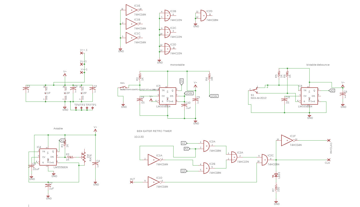
| The Eater 6502 parts kit: got that here.....partially assembled PCB, and an SBC external timer. A useful logic probe, based on an Arduino Mega, is also part of the BE 6502 project, vid for that is here. |
So far so good, but after finish all the fab, it took me about 3 evenings to get the SBC working, mostly because I rushed and made mistakes. Never rush.
Stupid mistakes let me count thy ways. First, I got an older version of the PCB, i.e., I clicked "add to cart" to save myself about 2 minutes--but instead, I should have read the project's webpage, downloaded the REV-B gerbers and gotten the REV-B PCB fabbed from that. The PCB's designer clearly states REV-B solves some design issues with REV-A, but I missed it. The author also clearly states: to get REVA to work I needed to add a 3K resistor to the bottom of the board, or the BE pin on the 6502 won't be held high, but, well, I missed that too. Until I used Sigrock Pulseview to determine the 6502 BE pin was kaput, and added the aforementioned kludge, I got zilch from the CPU. Time wasted: maybe 2 hours. Very nice!
I also put all the LEDs in backwards and also flipped the SBC's reset switch 90 degrees. I see these little 4mm switches all the time but did I really know how their contacts were laid out? No. 4mm switches are laid as per my drawing below: flip the switch 90 degrees and it won't work.

During fab I also had a scary moment; I decided to replace the RAM socket with a low profile 28 pin ZIF I had in my junk box, but lifted up a critical trace in the process.

Fortunately when I soldered in the ZIF and fixed every other mistake everything worked, which means the RAM socket trace must have still made contact--I got lucky. It was a frustrating few evenings, but, troubleshooting the REV-A board, using my PIVISA enabled bench tools, adding the missing BE kludge resistor and correcting other stupid mistakes proved educational; fixing something new almost always is.
 |
| Working SBC. |
 |
| My current setup for 6502 SBC action. Clockwise from left: ROM burner, LCD, timer, breadboard, and Arduino Mega clone used as a logic probe. In the center is the 6502 SBC. |
OK, so, beyond practicing patience during fab, what else did I learn? The crux of the biscuit is understanding basic Von Neumann architecture. That's the internal design most (if not all?) PC's nowadays use, including the Eater SBC.
(Von Who? No not this guy:)
 |
| Not me--"yes I worry". |
(Not this guy either:)
 |
| Wasn't involved in computer design as far as I know but, hacked strat clones, and is extremely important. |
This guy!!
 |
| John Von Neumann, who led the team that came up with the basic architecture of a modern PC. All hail-- outrageously brilliant dude--"The Van Halen of Computer Hardware". Fun video re: JvN is here. |
In this case: The Eater SBC's CPU, RAM, ROM, and peripherals share common elements: for instance, data, address, and read/write lines. What this SBC project drove home and what I felt I didn't understand is how each device (a RAM chip, a ROM chip, a graphics device, etc.) on the bus is enabled or disabled.
It's pretty simple: we use logic to trap a range of memory addresses then upon a match select a chip or device so it can read from or write to the shared bus, allowing the chip to do useful things. Otherwise: deselect the chip or peripheral so it leaves the data and bus alone. Once the chip is selected the CPU can communicate other things to it, such as whether to read data from it (eg: OE or "output enable" = low), or write data to it (e.g.: WE or "Write enable = low"). The Eater SBC uses a single 74HC00 chip to trap addresses and uses the 7400s' outputs for selecting the computer's various memory ICs as well as the LCD display for Read/Write madness.
These logic values, chosen when the PC or MCU was laid out, determines the device's memory map, a computer science term I never really understood. Now I think I get it.
So yes: this week's great chip select epiphany can be summed up in an abbreviated, back of the napkin drawing:

From here we can dig into how each chip, CPU, peripheral etc. works, giving us a way to understand things at a deep level.
Timing has to be considered--see the vid here--just because a chip or device is selected doesn't mean it will act quickly or slowly enough to make everything else on the bus happy. And of course, you need to understand how the guts of the CPU and attached devices work--study those data sheets--to be able to write useful assembly code.
Going forward: the PCBWAY-PCB for the REV A Eater 6502 SBC PCB has an expansion bus if you will--it brings useful signals out to a 40 pin header, and better still, there is room in Mr. Eater's SBC design to trap unused memory addresses (say 4000-4FFF?) to add more peripherals, perhaps something audio focused? But that's for a later post.
OK enough for now. It's Covid so i can't get on the local bus, but now, I can most-def get on the PC's bus. Which means yes, there are fumes, but at least they aren't diesel. See ya.