Showing posts with label Bipolar. Show all posts

CV Generator Part II--"Seems Working"

Readers: If you'd like to build the CV Generator featured in this post, please go to PCBWAY's Community pages--gerber file; KiCAD 9 project/pcb/schematic/library files, B.O.M.'s, and more, are here.  

You can also help out this blog immensely by checking out PCBWAY using the link here. Thanks!

==============

Just got back from a long and much needed vacation with the psychiatrist wife--back home and back to it. 

This time I improved the ATTINY 1624 based CV generator from this previous post--good news: hey, it works.


Synch issues with my camera made the OLED appear to drop lines of text but in real life the super cheap OLED display looks good.


Reviewing its features: 

  • Three -10 to +10 DC CV outputs, independently controlled from potentiometers (not rotary encoders). I like the way pots feel for this application; in general I dislike membrane switches and rotary encoders.
  • A 5V momentary switch for creating triggers with a dedicated output and LED.
  • Practical use of the ATTINY1624's super affordable high resolution mux'd AD conversion (details here towards the bottom of the post)--to see if I could get >12 bit oversampling using the analogReadEnh function in sketch (it works!)....This is killer feature that's surprisingly under-documented.
  • Eurorack footprint--this is going to go into my bench rack.
  • Test Points. TP1 can be used to test the MCU via a blink subroutine, or maybe some future expansion. TP2 should be adjusted to 2VDC using the 20K trimmer for bias offset for the final buffer stages.
  • A TX/GND serial port. For future expansion? Who knows. But I figured why not.
  • A port for UPDI programming. See previous post here (halfway down the post) and IMSAI guy video here.  
For firmware I used Arduino Sketch and IDE and the Greiman SSD1306ASCii library (here).  Firmware creation for the generator was pretty easy. By bringing analog data from the pots in at 16 bits, I could ditch a bunch of LSB's and get reasonable readings on the OLED that didn't jump around a lot. 

Some simple math converted the right shifted 16-bit value into a x = -10 to10 value for the OLED:

float scaleToPlusMinus10(unsigned int x2){
  x2 = x2 >> 8;
  return ((-10 + (float)x2 * 20.0 / 256) + .5  ;
}

The module consisted of 2 PCB's provided by this blog's patient and helpful sponsor PCBWAY: a main board with hardware on the front and the SMD components (1206 and SOIC--not too tiny) on the back, and an 8HP Eurorack front panel.  

I did a lot of the heavy lifting for the design during the initial build (post here). So this "rev 2" is a prettier version with a few improvements.

And--thankfully my measurements this time around were correct; everything fit.


USELESS BUILD PHOTOS


Always happy to get new PCB's from my sponsor, PCBWAY.  Even with the tariffs these guys are still way cheaper and faster than anything I can find in North America. Go A's!

I used an SMD stencil, solder paste, and a hotplate. This has become my go-to assembly process for most of what I do these days--it's fast....with some practice SMD hand assembly has become easier for fab, mods and troubleshooting vs. through-hole.  


I gloofed on a bit too much paste but fortunately it's a pretty forgiving process.


For the hotplate, I heated it up to 210C and it sat there for a couple of minutes, then cooled it to 150C.  This was all done manually from the plate's front panel. There appears to be way to automate this--there is some sort of temperature curve firmware in the hotplate--but I can't find any instructions for this in English. Sorry.

The hot plate process is surprisingly forgiving but I ended up with a few solder blobs on the SOIC IC's. Fortunately these can be quickly fixed with solder wick. 


Firmware test....

For the OLED I de-soldered its edge pins and used longer pins instead. This allowed the display to stand off from the PCB an appropriate distance. After putting items into place I tacked soldered the edge connector pins, removed the front panel PCB, and finished soldering.


As far as accuracy--the completed module is pretty good but not perfect. For what I do--cranking CV into whatever module I am messing around with on the bench it is definitely good enough. For better accuracy I'd probably need to use a rotary encoder and a 16-bit DAC. Maybe a future project? Update 3-30-31--I completed a "revision 3" of this design that uses an MCP4728 quad DAC. Still uses normal pots, not rotary encoders. It's more accurate--DC voltages are within a percent of the OLED's displayed voltages--but soldering MCP4728's, which are extremely tiny, can be tricky.  If you need more accuracy please check it the post here.


Overall, fun times; I might build a few more of these. 

Until next time, don't breathe the fumes.


3 Channel Bipolar CV generator Part I: Didn't Fit; Built it Anyway

Readers: this is a work in progress but you can get the files associated with this post from Github, here. 
(Update--Euro 'version 2' of this module is working, post is here).
===========

Back again! 

I wanted a synthesizer module that accurately output and displayed 3 independent control voltages ranging from -10V to 10V DC.  

The early prototype used a 3D printed front panel conforming to PAIA Frac format. Camera Synch issues meant my digitial camera couldn't capture all 4 lines of the working OLED but in real life it works.

There were a lot of ways I could have done this--using a multiplexed bipolar digital to analog converter (post for DAC here; multiplexer here) but instead employed the 16-bit ADC features of the impressive ATTINY 1624 MCU, covered briefly in this previous post. Overall, design for version 0.1 was simple; I used the pots configured as voltage dividers, buffered by op amps, took the 0-5V wiper voltages from the pots and connected that to ADC inputs of the ATTINY, and had the MCU feed a 128 x 64 OLED display to convey the 3x voltages.

Finally I used inverting op amps to get 0-5V DC from the pots to the -10 to 10VDC needed at output:  

One of 3 identical buffer subcircuits. A simulation of this simple inverting buffer/amplifier can be found here; I have posted the files for this prototype at Github, here. When the design is further along I will post files to the PCBWAY Community.

CONSTRUCTION

I laid out the design in KICAD 9 and used Arduino Sketch to (quickly) create the firmware. Because the ATTINY isn't blessed with buttloads of flash memory I used Bill Greiman's memory-friendly SSD1306ASCii library (here) to provide functions needed for the OLED. 

I sent the gerber file to this blog's trusty and most-excellent sponsor, PCBWAY. Very soon the boards were back. They do great work! You can help out the blog by checking them out here.

The prototype used 1206 SMD components, a stencil, and a Eurorack formatted front panel. After years of trying different workflows, this combination seemed a decent mix for fast prototyping, flexibility in terms of modification, and small size. 

After unbagging and inspecting components I discovered a major mistake: the PCB was too tall to fit into a Eurorack or Frac enclosure:


I contemplated pitching the entire thing and starting again, but instead consulted the guys in my audio geek discord group. Could this be fixed? No, but, one member suggested I try to build it anyway, to shake out the first batch of mistakes, before going to Version 2. Good idea....

I got building....

Used my $35USB hotplate for SMD, works great.

 
Original design incorporated Eurorack power, but I adapted this to Frac Power using edge connectors, 22 gauge hookup wire, and shrink tubing. This allowed a fair amount of twisting and bending without breaking wires or shorting connections.

Same idea for the rest of the hookup wire....


Initial tests showed way too much current draw for the positive rail--should have been more like 4-5mA, but here it's 230mA. I pretty quickly traced this to a 78L05 regulator being installed upside down, due to using the wrong Kicad footprint--I used the 3N3904 footprint, not 78L05, so Pin 1 and 3 were flipped. Whoops. I pulled the 78L05 using a Hakko FR301, flipped it, and resoldered. Surprisingly this snafu didn't blow up the MCU, nor the regulator.  


With the power problems sorted, things seemed to work--albeit not terribly accurately -- off by as much as 5% at times--but OK for the first attempt.


I laid out a quick-and-dirty front panel for the PCB using FREECAD 1.01.

....then mounted the PCB to the 3D printed front panel:


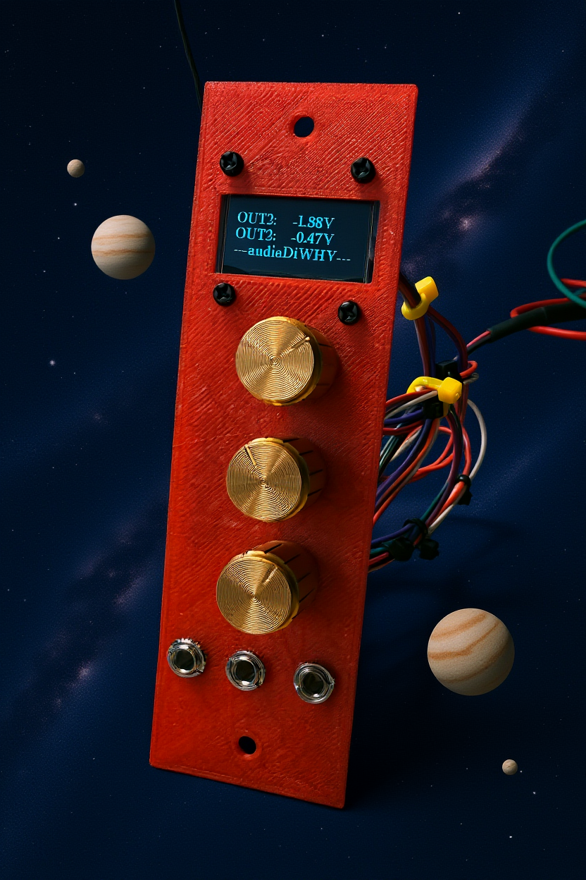
Version 0.1, unpowered, in the flesh...


Version 0.1 seen through the lens of open source AI (ComfyUI + Flux Context Dev with a 12GB Lenovo/Nvidia RTX2000 GPU).  This first and only pass through the AI algo took 50 seconds and beat the holy crap out of what I could have done with an hour of organic intelligence and Photoshop--if this doesn't scare the hell out a tech + graphics professional, I don't know what does.

OK, quick post but enough for now. I will keep plugging away at this project and hope to have a revision with better accuracy in the coming weeks. Update 8-28-25: Eurorack "rev 2" version of the generator is complete and works....please see the post here. 

Update 4-2-26 "rev 3" with a MCP4728DAC driving the 3x CV outputs, giving better output accuracy, is online: post here.

So--until next time: don't breathe the AI.

Analog Devices AD5761--EZ Embedded C library for Bipolar DAC--Works!!

 Hi again, follow up from the last post, where I was wasting hours trying to get an AD5721 12 bit Bipolar DAC to work. 

Giving up on that, but I got the AD5761, a more expensive version with 16 bit resolution, to work just fine.  

Through an EE I know, he confirmed via AD tech support that the 5721 uses the same code as the 5761, except that the data register is a bit different, so that's not the problem.  

Something on my bench? Phases of the moon? We may never know.

So my solution about getting the AD5721 to work on my bench is simple: don't use it! The 16 bit version is about $3USB more per chip; that will have to do.


They both don't work!


This one does! 

Looks OK on the scope....

I did learn an important thing about Analog Devices ICs--for some (many? most?) Analog Devices provides really thorough open source example code, written in C.  

For the AD5761 for instance, go to its "product overview" page on the AD site (here) and scroll down.  

You see the "NO-OS driver", go here. Wow--There is a lot of  C code here to peruse and if you are feeling lazy, just use that in your embedded C project and call up the methods Analog Devices provides. 
Cool.

For me, I am only going to use this DAC in a very specific application--bipolar DAC for +/- 10V P/P.  Otherwise I'd use a less expensive DAC.

I need to send a 16 bit word in, in straight binary, and need that value converted to analog at the chip's output. If I end up using this for +/- 5V, 0-10V etc. etc., I can write new functions, it's only a matter of changing the 24 bit control register that tells the chip what you want to do (which again is cool).

If you want to get my super easy embedded C micro library for this, the Github content is here.  If you fork this dork, please comment below, let me see what you did, I am interested in seeing what others do to expand/improve/correct this code.

In the meantime, this all took way, way longer than it should have, and I am a bit burned out and frustrated. I guess we can't have fun all the time, right?  Coding means no fumes, but a lot of sitting around.....

Enough! See ya next time.

Analog Devices AD5721: welcome to BIPOLAR DAC HELL!

Hello again. I've not been posting as much lately due to health issues, but still had time to mess with some new ICs on the bench. 

This time I went to war with Analog Devices AD5761/21 bipolar DACs.  

AD5721/61 requires +/-15V, a 2.5VReference, 3 data lines for SPI, and 5V to tell it what is logic "high".  Add Pulseview to analyze why it doesn't work and you have a lot of bench clutter.

DACDAC go: The advantages for audio design using a bipolar DAC, especially one with a buffered output like the AD5721/61, is lower chip count.

Hook a bipolar DAC to your MCU (for me, on the bench, an Atmel 328P on an Uno R3, programmed from Atmel Studio 7), write a few lines of C code and the result is a nice bipolar ramp wave--or any other bipolar low frequency analog signal--at the DACs output. No need to use op amps and/or caps to get the output to straddle 0V.

Perhaps an entire complex AudioDiWhy circuit can be built using only two chips and a few caps: the MPU and the bipolar DAC IC.  16bit fidelity. 20hz-1Khz or so waveforms. Low noise floor.  Nice!!  


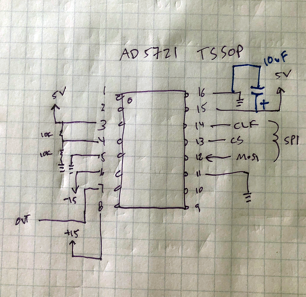
Minimal write-only wiring for TSSOP version of the 5721/61. You can use 2.5V from a bench psup for pin 4, which is the DAC's reference, instead of 2x 10K resistors from 5V to ground. If you want to read data from the 57x1 as well as write to it, wire Pin 10 of the DAC to your MCU's MISO pin. WARNING! Wiring for the LFCSP version of this IC is different--don't misread the datasheet.....  


These 2 DAC IC's are a bit expensive--the AD5761 is 16 bits and costs about $10 USD in small quantities while the AD5721 is 12 bits and costs about $7.  

One the projects I've been thinking about only needs 12 bits, so for starters let's be frugal and use that.

The AD5721 is a very tiny IC and we need to make it ready to breadboard. OK, for tiny tiny tiny SMD to DIP applications I like Schmartboard--more expensive than most SMT to DIP adapters but quick to fab and easy get right. And sometimes they have blow-out sales, which is how I got these adapters for about $1USD each.  

On paper the AD5721/5761 has some other cool features, like the ability to change its output range from your code (no need to use a processor pin for this). Also the ability to read what is in its registers back to the MCU via SDO > MISO. It can output its temperature and daisy chain several of the DACs together for multi channel output. 

Cool!

OK that's the good news, but here's the bad news: I worked for about 3 days to get the AD5721 to do anything (other than just sit at 0V at output) and--nothing

Welcome to DAC HELL!!!! 

I swore, laughed, and I cried. I sat up at night trying to brainstorm what I was doing wrong. I went into full OCD mode complete and at times was not able to talk to anyone. 

I read over the data sheet 1000 times then another 500 times to be sure I didn't miss anything. I poured over the timing diagrams and used Pulseview to verify SPI was within the chip's speed limits and the chip was receiving the SPI traffic intended (it was). 

It could have been my chip?  My SMT to DIP soldering work? 

I built a second one. Same thing.

I tried all different variations of my code.  Nope. No output.

I was coding it wrong?  Um, from the data sheet, I am going to say no. But maybe--yes.

I need to explain this.

First let's talk about how to program this little beast. 

As DACs go, this one is a bit harder to set up than say a MC4725 but really it's not that bad. 

The AD5761/21 uses SPI. It needs to see 24 bit words but that's easy--pull CS down, send your clock and data using 3x SPI transmits, then pull CS back up.

So......

  • Power up
  • Send a reset (a byte followed by 2 "don't care" bytes)
  • Send 3x control bytes to tell it things like what output voltage range to use
  • Send a byte to say "send the next 2 bytes to the DAC register"
  • Send two bytes to the DAC register.  That's the data you want at output.
  • Wham Bam--you have output.  Right?  
  • Um, with the AD5721, no.  I tried.  I really did try.
So working psuedo code might work something like this:

CS low
 7 0 0 // soft reset after power up
CS high

CS low
 4 0 0 // control bytes; we want +/- 10V at output
CS high

CS Low
3 255 255 // write 0xFFFF to dac register, which puts voltage at DAC's output.
CS high

 Nothing worked, so I tried the 16 bit version, the 5761.

YES! Dropped it in, same code, same bench setup, same footprint--it worked!!! 

Output from AD5761, see how easy that is?  TWO POINTS!


But same everything with 5721 (again, I tried two) NOTHING!  

I will skip the photo of the scope flat lining.

I have read the AD5721 datasheet more times than I've perused barf bag instructions on a commuter plane--says other than the 4 LSB's of the data registers being "don't care bits" on an AD5721 there is no difference between the 2 chips.

The input register on the 5721 ignores the last 4 bits, but the control bits for BOTH CHIPS are documented as being 24 bits wide. 

How can that be when the 5721 ignores the last 4 bits?

So my guess: the control words for the AD5721 must be different than the 5761. That's why the former doesn't work. And AD didn't document this difference in the datasheet correctly.  (right?)

And oddly I see posts online for AD5761 uses, libraries for it, etc., but really nothing for the AD5721.  

Does anyone even use the AD5721?

Maybe someone can enlighten me, if you have ever gotten an AD5721 to work please, please comment and let me know the data words you used to get the chip to do--anything.

But for now it's 16 bits for this project. 

I am going to see if anyone at Analog Devices can tell me what i am doing wrong for the 5721....but they are big, and I'm not, and I may be out of luck.   

Update 7-19-21 after asking around and calling in a few favors, I may be able to have a pro EE help me sort this...he has contacts at AD.....AD says no, the control register for AD5721 is 16 bits, in spite of what the data sheet says, so that's not it....16 and 12 bit chips should be interchangeable, but really, they didn't know, and figured I was doing something wrong....to their credit, I am told Analog Device's support on this matter was attentive, polite, and overall top notch.

UPDATE-7-24-21  Giving up on 5721 but the 16 bit version works OK.  See the post here. This one goes into the "never figured it out" crap can. I gotta move on......