Tuesday, January 30, 2024

Rotary Encoder--Hardware Debounce

 Readers: If you want to build the project featured in today's post, please go to PCBWAY's Community pages--a gerber ready to download and/or fabricate as well as KiCAD files, PDFs, a BOM, etc., are here.  

Also please visit PCBWAY's site using the link here--it will help this blog immensely. Thanks.

======

Hidy Ho! Welcome back for more blog fun. 

I have been super busy with my day job--correct, I don't blog for a living. 

But I've had a tiny bit of time this month to work with Elton at Otter Mods to design a small PCB for debouncing a cheap rotary encoder.

For a background check the post here

I got a $2USD clone rotary encoder to "work" with an RP2040 and 1306 display, but try as I might I couldn't craft an effective algorithm in C to debounce the cheesy thing. 

Sure, there is a takes-no-brains-to-use debounce library for Arduino, but dammit Gil Amelio we are no longer in Kansas--I tried to port the C++ Arduino library into something for RP2040 and so far no dice...not enough time.

Is it a cop out to use hardware for this? Well, maybe, but here it is:


The Encoder hardware debounce board; available from the blog's generous sponsor PCBWAY. Get it from their community site here.


SE HABLA HARDWARE?


Elton at Otter Mods and I passed some KICAD schematics and PCB ideas back and forth, and here's what we came up with:


R1 and C1 integrate the encoder output while the 4011's make things into a nice clear rising or falling edge. Q1 and Q2 buffer and invert and set the logic "high" level.

Laying out the board in Kicad was pretty easy.  I used SMD 1206 parts where I could--they are easier to swap out vs. through hole if a value change is needed; no solder sucking--heat up the SMD part, get it out of there with tweezers, and drop in the new part.

I only had DIP 4011 IC's so that's what ended with on the PCB.  

To buffer the 4011 outputs and bring the logic levels up to Vdd I could have used a lot of things but ended up employing trusty 2N3904 transistors: they were what I had lying around.

This was a super easy build--fab took less than an hour and worked the first time. 

As far as mistakes: a few of the legends on the board were incorrect; this is fixed on the 1-29-24 version I uploaded to PCBWAY. 

Otherwise, the board seems to be A-OK.

Some useless build photos:

Happiness: unbagging the boards....

"SMD ahoy"


Oops, extra solder bit by the 4011, and note the Sharpee corrected legends, but hey it worked.


Testing....

The result is super clean edges for the encoder outputs, instead of the hash and scrambled eggs the encoder produced on its own.

Scope at 500uS per division--using the PCB the encoder state change produces a clean rising edge--good enough for what I do.


OUTTRO


I am still looking for the killer software debounce algorithm, but in the meantime, I see this RC/4011 idea used for debouncing and "quickly rising edge" square wave creation.  

I figure it'll work no matter what MCU or digital doodads are in your design. 

I have a Moog hi-pass filter clone on the bench to next blow up; also, I am considering employing the debounce/encoder madness in this post into some sort of simple clock multiplier. Hope you can stay tuned.

Monday, January 1, 2024

Vactrol Envelope Follower: Double Sided SMD Fabrication

 Readers: If you want to build the project featured in today's post, please go to PCBWAY's Community pages--a gerber ready to download and/or fabricate as well as KiCAD files, PDFs, a BOM, the front panel gerber etc. are here.  

Also please visit PCBWAY's site using the link here--it will help this blog immensely. Thanks.

======

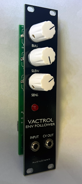
This time I revamped a circuit I laid out a long time ago--a envelope follower based on a 5C3 Vactrol.  

The reason: the original  module was large; could I shrink the size of the module by putting all hardware and SMD components on a single PCB?

Sure.

HISTORY

I began exploring envelope followers when I got a Mutron III decades ago, a stompbox I seriously wish I still had. 

It's a filter fed by control voltages derived from the amplitude of an incoming audio signal. 

The Mutron (schematic here) responsed to the incoming amplitude in a way I found musically pleasing. It uses a 0805 opto coupler; to get its slow, sloppy feel I breadboarded the amplitude to CV subcircuit based on a 5C3 vactrol

I found the Vactrol version useful for things other than auto-wah--used in front of a VCA for instance I got some interesting audio compression effects.

Soooo...20 years later I wanted to see if I could make a smaller version of this for Euro....to get it to 6HP I had to put SMD parts on both sides of the board.

Thanks to PCBWAY for sponsoring this blog....new boards are back from them....

Turns out the layout (in Kicad) was a bit tricky since I had to keep straight what parts were on what side of the board; where it made sense to put vias, etc., but after a bit I got the hang of it.

SMD parts on both sides....


I used a small vice to hold the board in place while I soldered SMD parts (I have settled for now on 1206 and SOIC, which are large enough to not always require a microscope for hand soldering).


The board and module worked first time. The only thing I'd like to redo is the front panel, which could be laid out to make the legends easier to read from a distance. 

Overall I thought hand soldering SMD parts on both sides of a PCB, including SMD electrolytic caps, would be challenging, but no--this was a piece of cake. 

Using the Vactrol EF

Plug in a preamp'd guitar or clav; the EG CV out goes to a bandpass filter; turn the EF's three knobs until the LED lights the way you like; riff on like Jerry Garcia and Stevie Wonder.  

My goodness, it was 1984, it's 2024 already. See ya next time.

Anything to Clock Subcircuit

Readers:  If you want to build the project featured in today's post, please go to  PCBWAY's  Community pages --a gerber ready to dow...