Git and Github: Crash Course

Hello again--this post isn't about audio, hardware, MPUs, soldering, DACs, or even electronics tools like EDA's and scopes.

Instead, I present my lab notes: how I have configured GIT/github, a popular version control system, for my various development computers. Excitement.

Why the kitten with the octopus tentacle?


Intro: WHY USE A VCS?


Even a small potatoes software developer like me needs version control. 

Before using GIT for version control I wasted a lot of time screwing up/making working the code worse, then spending hours cursing while I got the code back to a point where it functioned.

Before breaking my code, did I save a copy first?  

Nope. 

Enough! 

I have been a big advocate of VCS's since the early 2000's (Gnu CVS).

Nowadays I use Git, but don't use it often enough to remember the anything beyond the basics--that's why we use AI, I mean: that's why we write things down.

If you are a beginning programmer and want to learn a bit more about this free VCS--"version control system"--Git is the most popular VCS nowadays--this content might be of interest.  

If you know GIT better than I do--I only know and use maybe 5% (?) of its commands--you're probably going to want to skip this one. EVEN BETTER: if you are an experienced Git user, please read this post; where you find it oversimplified, misleading, or incorrect, please comment so I can improve and better learn GIT.

WHEN U ASSUME?


Assumptions:
  • Your development computer has GIT installed--if not installation details are here.
  • You have some previous experience with version control software or at least knows what it's used for/why it's important.
  • You have a user identity already set up on Github (mine is "cslammy"; yours isn't)--if not, get one; New user creation is well documented--go here.
  • You use SSH to securely communicate between your dev system(s) and Github--there are other ways to do this, but I know SSH pretty well so it's what I use and what's covered in this post. 
  • You are setting the whole thing up "from scratch", otherwise, if your SSH keys are already set up, skip that step below.


FIRST STEP: CREATE NEW REPO ON GITHUB

Log into github.com with your assigned username.

Click on the repositories tab at the top

Create a new repository. 

IMPORTANT FOR SECURITY: choose "private" if you have any keys in your code...for instance, an API key. I created a new a repo that was public but had a private key in it in clear text.  Fortunately an admin from github saw this and shut down the repo, then, emailed me to tell me about my mistake.  

I had to delete the repo, change the key, and start the whole process over.  You don't want to have to do this, so, be careful.

Do not add files, license info, readmes, etc., to the repo at this time.

NEXT: SETTING UP SSH


============CREATING PASSWORDLESS SSH=========== 
 

On your development PC(s) install OPENSSL if needed.

For UBUNTU desktop (I use 22.04 currently), openssl was already installed; nothing to do. If not? different distros have different installation steps. As a Ubuntu/Debian/Mint guy, for me it would be something like this.

For Windows: get cygwin64, install using defaults, and add C:\cygwin64\bin to %PATH%. This will allow opensll (needed for keygen) to run from Windows command line ("cmd"). Step by step instructions are here.

===========SSH PRIVATE AND PUBLIC KEYS===========

For a machine to talk to github using SSH you have to create SSH keys, store the private key locally, and upload the public key to github; details here.

The following command creates a public/private key pair in ~/.ssh on linux; the same command works for cygwin Windows:
 
ssh-keygen -t ed25519 -C [github assigned email address]

so for me:  

ssh-keygen -t ed25519 -C cslammy@github.com

note: use the default name suggested by your OS for your public/private keypair. If you rename your keypair your secure connection to github may never be established, or, may break.

note: rename ed25519 and ed25519.pub if they already exist.cat

note: why "cslammy@github.com"? Why not the gmail email address I associated with my github.com account when I first created an account?

It's the way Github works: each user gets a github.com email address when they join github.

This Github assigned email is used for SSH key management; you use git@github.com in the git CLI for ssh remote, but you use your personal email address (e.g.: foobar42@gmail.com) for other github related things, like getting emails from the github community.  

These 3 different logins/identities confused me at first....it made more sense after I used git and github for awhile.  

Like it or not, you will need all 3.
 
========POTENTIAL LINUX GOTCHA?=========

Check that the generated keys are copied to ~/.ssh by default.

On one of my ubuntu hosts I saw that the keys were not stored in ~/.ssh directory. 

or maybe I didn't choose to save to default location?

As far as I can tell, the keys (at least private?) need to be in ~/.ssh or SSH to github will not work!!

If they are not there:
  • Figure out where the keys got stored (maybe in your home directory?)
  • Note existing CHMOD's/CHOWN's for private and public keys
  • Copy keys to ~/.ssh directory
  • If needed, CHMOD and CHOWN copied files/folders to match originals.

===========UPLOAD PUBLIC KEYS TO GITHUB===========
 
On the dev system's ~/.ssh folder that has the private key there will be a public key; its filename ends in .pub.
  • Cat the .pub file or in Windows open it in Notepad.
  • Copy the .pub text content without any spaces, extra lines, etc. to your clipboard.
The public key will look something like what you see below, which is an example, not a real public key:

ssh-ed25519 AAAAC3NzaC1lZDI1NTE5AAFBAAIFo+Zumzwrm/DsmDqJCZLJQQmr4CA5Qhgb2TyxI1gtqX cslammy@github.com

Then:
  • Go to github.com, log in
  • Click on your profile icon in the top right of the main page.
  • Go to settings > ssh and gpg keys > ssh tab
  • Upload the SSH public key text to github (more here).
NOTE: as far as I can tell, the public keys uploaded to github don't stick around forever. You may need to re-upload your public keys from time to time.

============ADD GITHUB TO KNOWN HOSTS============

I have only seen this on Linux, and only occasionally,

ssh-keyscan github.com >> ~/.ssh/known_hosts #Not sure this was needed

Did it work?
➜ .ssh more config
Host github.com
HostName github.com
User git
IdentityFile ~/.ssh/id_rsa
 
Was/is this is step needed? Probably not.

=========TEST WITH SSH===========

From a system that has the required private key etc.

ssh -T git@github.com

Note you use git@github.com as username/domain, NOT your git username (for me, cslammy....) 
(or)

ssh -Tv git@github.com #includes verbose debug info.

If if works, you should see something like this:

Hi cslammy! You've successfully authenticated, but GitHub does not provide shell access.

NOTE: Again, you must use git@github.com<mailto:git@github.com> when testing SSH protocol to github. Not some other username. 


SETTING UP THE REST


=========GIT CONFIG ON YOUR PC=========

Git has a lot of configuration options.

One is to make sure to set: that the default Git branch is “main” locally.  That will match github.com’s default. 

You have to change this for at least some Linux distros--local default branch for Ubuntu git for me last time i set up git/Github was “master” which did not match the current Github default.

On linux or Windows, from terminal:

git config --global init.defaultBranch main

From:

Next, set how carriage returns are handled for your OS--different for Windows OS vs. Linux....details here.

For Linux development systems: 
git config --global core.autocrlf input

For Windows development systems: 
git config --global core.autocrlf true

Next, choose VSCODE as your editor for things like git commits: 
 
git config --global core.editor "code --wait" 

Finally: consider setting the rest of the default features described here; kitchen sink details are here.

========GET THE URL OF THE NEW REPO==========

Create new github repository at the public github website (how-to is here).  
**DO NOT ADD ANY CONTENT YET**
  • There is a green button called CODE in the new repository
  • There is choice for what to display: SSH or HTML.
  • click on SSH
  • You will see a URL looking string to use for SSH to this new repro; here is an example.
git@github.com:cslammy/AD9833VCO.git 

Copy this to clipboard, save it to Word, save it to notepad++, whatever.  
You will need this again shortly.

==========LOCAL DIR AND GIT INIT=======

Create new directory on local Linux or windiows machine for the new project.

(or)

CD to an existing directory where you already have some code.
 
issue this command:

git init

This creates .gitignore, DB files etc, for any data in the directory.

Note: if you want to get rid of git for the project (Linux):
  • go to the root directory for your project
  • ls -la
  • delete the .git directory:  rm -rF .git
=====EDIT YOUR .GITIGNORE FILE ==========

.gitignore basics are here

.Gitignore is a text file that tells Git what files and folders you don't want to version control. 

You will probably want to modify .gitignore for each project you version control--otherwise a whole buncha crap of you don't want to replicate will replicate (such as a "build" folder and all its contents, created by cmake).  Doh!

A pretty typical .gitignore file for me, for VSCODE/CMAKE coding, that seems to work, has only 3 lines:

Deprecated
deprecated
build 


Deprecated is where I put anything no longer salient to the project; docs are things like PDFs of IC's used. Whatever. Up to you.

============SETTING UP PUSHES AND PULLS==========

Now that we have the above steps, next, let's set up the commands we will use to securely send and receive data to github...we are not doing the actual push yet, rather, configuring git locally so we can push and pull data later.

To do pushes and pulls git uses commands like this:

git push [variable] [branch]
git pull [variable] [branch]

First, think of a variable name, a common one in our situation is "origin"

Make sure your variable isn't already set. If it is, you want to get rid of it.

DANGER! Failing to do this can lead to all sorts of problems.  

open terminal and CD to your project's directory.  Then run this.

git remote -v

if you already see an "origin main" pointing to a different repo, you need to get rid of it (or choose another variable).

git remote rm origin  #remove "origin" as variable.

Then, set a git variable to represent the remote repository. You can reuse origin.
 
Here is an example:

git remote add origin git@github.com:cslammy/AD9833VCO.git
 

[Branch] is the info you wrote down or copied into clipboard or notepad....will look something like this:

git@github.com:cslammy/AD9833VCO.git 


...where AD9833VCO.git is the name of a repo folder you want to push to.


======README AND LICENSE=========

Optional, but I do it: on the local system, for public repos, create a README.md and a License file. 

Then:

=====DO AN INITIAL PUSH OF FILES FROM GITHUB TO LOCAL====
 
Assuming I already have some code in my project folder, I do a git push first.

Git needs to know about your work so far...git status says what needs to get uploaded; git add . adds everything except gitignore files and folders to the queue, and git commit gets everything packed up and ready to go:

cd to your project directory if you aren't already there, then:

git status
git add .
git commit -m "initial upload"

Then, use this to push files for the first time to github.

git push -f origin main
 
After successful push you will see your local files in your new repo online. 

And...if it worked, you will see something like this:
 
git:(main) git push origin main
Warning: Permanently added the ECDSA host key for IP address 'x.x.x.x' to the list of known hosts.
Enumerating objects: 13, done.
Counting objects: 100% (13/13), done.
Compressing objects: 100% (12/12), done.
Writing objects: 100% (13/13), 6.52 KiB | 667.00 KiB/s, done.
Total 13 (delta 2), reused 0 (delta 0)
remote: Resolving deltas: 100% (2/2), done.
To github.com:cslammy/SYNTH.git

You now have version control working and your precious code in more than one storage repo. 

SUCCESS!

========PULLING DATA from github to local============

For whatever reason you added or changed data on the github repo using your web browser; now, you want to pull those changes back to your local dev system.

git pull origin main  #pull repo adds/changes to local dev system
git config pull.rebase false  #make the local DB whole by merging it                                 #with remote db.


========ESSENTIAL COMMANDS FOR VERSIONING=======

Once your git/Github setup works you can use the gazillion other commands (reference is here).

Obviously I won't go into all of it here--just the basics, ma'am.

A good command to see what changes you have made since the last commit:

git diff

OK, you've made some code changes, now you want to get save your changes as a new version.

git status
git add .
git commit –m “added foobar function to main.c”  

If you just say 
git status
git add .
git commit

your commit notes will be editable in your text editor--which you can configure using git config, how to do this is here.

Finally push the changes up to the cloud:

git push origin main


 ======GOING BACK TO PREVIOUS SAVED VERSIONS=====

git log

this shows the messages you tagged to each commit and its commit ID 

Once you have locked in on the ID you want to roll back to, here is the command to roll things back.

git reset --hard 0ad5a7a69ab9240da

=====DIFF CURRENT CODE AND LAST COMMIT===========

I use this all the time, useful not just for version control but to see your last bread crumb trail

git diff


OUTTRO


Wow already a long post, and this post only covers extreme GIT basics.
 
I will be adding to/correcting/updating this post as time goes on and I have git projects in front of me. 
I am revising code for a RP2040 clock multiplier, that will have a fair amount of embedded C and need a gitload of work. 

Will it work? Who knows?  Hopefully more about that project in the next few posts.

Son of Anything To Clock--LM311, Lower Parts Count

Readers: If you'd like to build the project featured in today's post, please go to PCBWAY's Community pages--a gerber ready to download and/or fabricate as well as KiCAD files and a BOM are here.  

Also please visit PCBWAY's site--using the link here--it will help this blog immensely. Thanks.

====

Last post I described a subcircuit that would take an audio signal from maybe 50K to below audible frequencies and turn it into a square wave--useful for turning audio into a clock signal for an MPU. 

It worked, but discussion ensued at my geeky audio meetup: is there an easier way to do this? 

Of course there is....Elton at OtterMods had a similar circuit, with lower parts count, based on an LM311 comparator.  

This post I'll discuss Elton's design, the LM311 comparator and build a prototype break out board ("BoB").


The Design:


How it works....

D1 turns a bipolar input at J1 into a signal at 0V and above.  

That's fed into the inverting (-) input of the LM311. 

The non-inverting (+) signal is the reference, with 12V for Vcc, the 47K and 10K divider sets pin 2 at about 2V.  

R5 sets the duration of the output signal.  

The LM311 needs a pullup resistor (R7; 1K) while the 2N7000 FET and R6 re-inverts the output.

About the LM311

This chip was new to me....Elton is super cool and gave me a few LM311 DIP IC's to try out.

An excellent overview of the LM311 can be found at DIYODEMAG: here .  

The LM311 datasheet is here; NatSemi application examples (untested by me, and knowing National, untested by NationalSemi as well?) can be found here.

LM311 is a good choice for low parts count comparator applications because its output is buffered with an internal NPN transistor:


A pullup resistor at "Collector Out", 3VDC to 15VDC at Vcc (pin 8), GND at pin 4, and a reference voltage (can be ground presented at pin 3, the non-inverting input) is all you need; let the balance and bal/strb inputs float; finally, tie EMIT OUT to GND. 

We are talking 2 components: the IC and one resistor, to get a fully working, reliable, fast comparator. 

The 2 component comparator.  For the pull up resistor: 10K should work.

A few more LM311 benefits:

  • Vcc to Vss can be 36V apart before you blow up the IC. Since we synth and audio nerds often work with +/-12V or +/- 15V for our voltage rails: good fit. 
  • Simple operation--if the non-inverting voltage at pin 2 exceeds voltage at pin 3, the output (pin 7) goes from hi-z to low. 
  • Unlike an op amp, the 311's the inverting and non inverting-inputs aren't virtual grounds--you can see the incoming signals on pins 2 and 3 with a DVM. 

THE BUILD 

Elton emailed me his schematic and I laid out the schematic and PCB in Kicad

I created a gerber and off it went to this blog's patient and enthusiastic sponsor, PCBWAY.

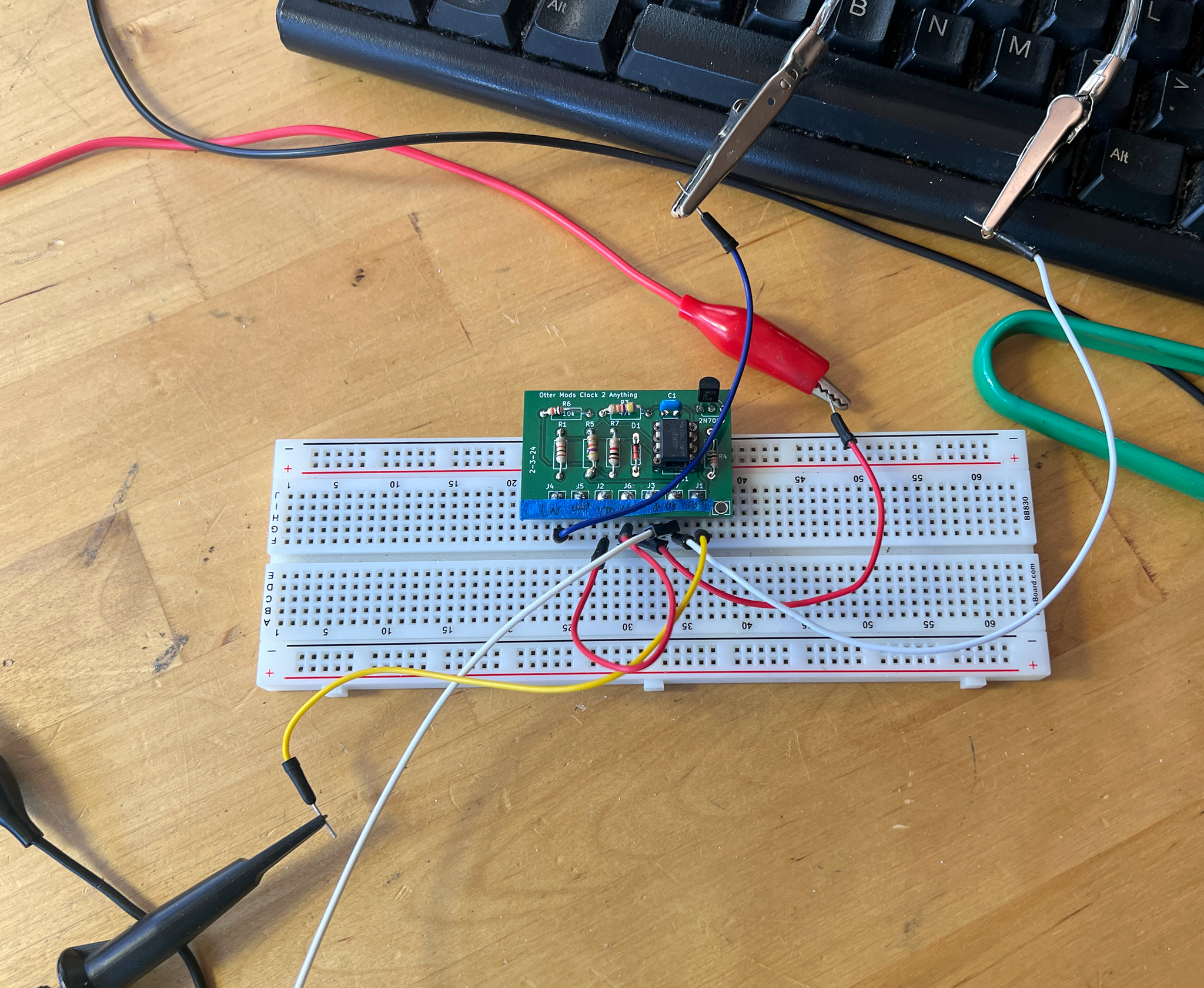
In a few days PCB's were in my mailbox:

Wham Bam, boards are back from PCBWAY. Please help out this blog and check 'em out.

Like the BoB in the previous post, I screwed up silks below the pin designations; pin numbers are wrong, and what pin is what?  

To make the BoB easier to breadboard I used 200mil edge connector pins; I bought some 100mil pin header male to male material, broke off a 14 pin section, and using needle nose pliers pulled out every other solid wire.

It took me about 15 minutes to solder the parts to the board and connect the pin headers.

The IC went in then I dropped the BoB onto a breadboard to test.

And at output I got--nothing.  

The output was slammed high, against the Vcc rail.  

Hello? 

This circuit was so simple, no way it could go wrong.

I probed the 311's pins, and Pin2 was 12V, not 2V.  

Hello?  

No issues with soldering or traces.  

After some fear and loathing: instead of a 47K/10K voltage divider, I errantly used a 470 ohm resistor  for R3. 

A 470 and 10K voltage divider provided, as a reference voltage, about the same thing as the divider's source voltage.  So no, this won't work.

Easily fixed--once I put in the right value resistor!!

"One of these things is not like the other" 

With the correct resistor values: "seems working"

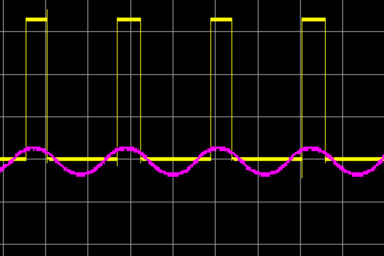
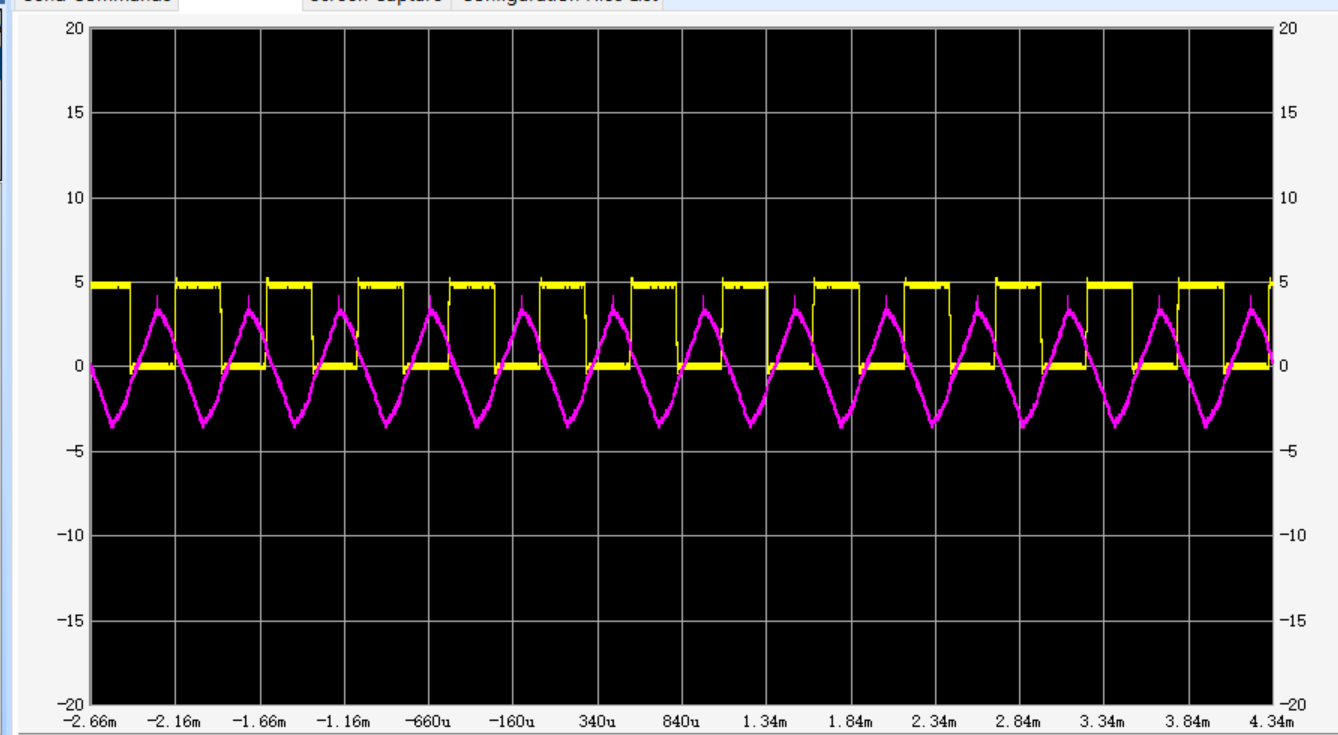
Elton's design worked great, nice clean square waves regardless of a sloppy signal at the LM311's inverting input. 

The BoB featured a low parts count--and, if going forward I used an SOIC LM311 and SMD resistors, this design could get really small. 

UPDATE: 7-27-24 I did another run of Ottermods' design, correcting silkscreen issues for pins J1-J7.  This rev2 gerber can be found on the PCBWAY Community site. Many thanks to the folks at PCBWAY for helping me update and improve these community projects.


Updated board with improved silkscreen legends


ramp to clock...

random to clock...

Sine to Clock....

Tri to clock....

So what's next? I hope to use this BoB for input buffering and rising edge detection for a clock multiplier, perhaps based on an RP2040.  

But! With my day job going full swing post-pandemic, will I have time? We will see.  


Anything to Clock Subcircuit

Readers: If you want to build the project featured in today's post, please go to PCBWAY's Community pages--a gerber ready to download and/or fabricate as well as KiCAD files, PDFs, a BOM, etc., are here.  

Also please visit PCBWAY's site using the link here--it will help this blog immensely. Thanks.

For upcoming projects I needed a breakout board to turn any waveform in the audio frequency or low frequency range into a pulse wave. Then: use the output's rising edges and throw an interrupt on an MCU.

So, I needed a comparator; lots of ways to design and lay this one out, easy. 

I also needed a few more features....

What I came up with:


DESIGN

As usual I recycled ideas used in previous projects. 

The MCP6002, an op amp I discovered looking at buffer sub-circuits from Mutable Instruments, provided clamping. An easy way to clamp J6's ground to positive voltage was to limit the MCP6002's power pin, Vcc, pin 8, to 3.3 or 5 volts--whatever voltage my MCU expected. 

The MCP6002's output will match Vcc--easy.

Warning: for any circuit that uses an MCP600x, do not supply greater than 6VDC to its Vcc pin--exceeding 6v may damage the MCP6002.  If you need to use a larger voltage (say +12VDC for VCC) consider using a different op amp--pretty much any dual op amp will work, but you might lose the MCP6002's nifty clamping characteristics.

The MCP6002's second stage provided an inverted output, while J7's non-inverting output voltage was determined by the voltage present at Vdd and not constrained to the clamp voltage.

VCC-VDD jmp wirepads could be shorted with a small jumper. This allowed the Vcc and Vdd to be supplied by a single voltage source.

The diode in U1A's feedback loop made U1A a precision rectifier, the same idea was used in a VCO triangle to ramp converter.

A final "feature": I could change output shapes with one additional part: C4. C4 can be omitted, but its value along with R2 provided a simple active filter, allowing different output shapes at J6 and different pulse widths at J7. 

With R2 at 1K, values for C4 could be anything from say .01uF to 4.7uF and beyond. Omit C4 to get decently fast rising and falling edges at J6 and J7. 

BUILD

New boards from the blog's sponsor, PCBWAY.  


100mil spacing for breakout boards presented a challenge to me, so I laid out J1-J7 200mils apart, grabbed some inexpensive 100mil edge connector material, and pulled out every other wire with needle nose pliers. 

Now I have a 7 pin edge connector with pins 200mil apart. This made the board a lot easier wire up I thought and worked a lot better than anticipated.


tested...worked!


OUTPUT--WORKED!


Simple circuit, simple results.  Purple trace is input, Yellow trace is output; screens were captured with Siglent's easy to use.  This was what I was after. 


So--I made a few errors with my silks but otherwise worked first time!  When was the last time I saw that?  

Onward!


Python: Digital Audio and DSP--Baby Steps

A goal for 2023--I will blame my tardiness on the pandemic? was to start down the difficult path of teaching myself Digital Signal Processing.

Audio is a good vehicle for this pursuit: there're a lot of good programming examples out there, and every DJ loves delay.  

Question: what platform to use for experiments? 

After research I chose Windows and Python. Windows machines are everywhere; Python is free and easy, and perhaps the path of least resistance.


Before going further: fair warning: Like the last post about learning C++, this post forms my trail of breadcrumbs through my learning process--instead of writing this information in a notebook for later review it's in this blog. 

So: mostly useful to me, maybe not a lot of others--I expect like 5 views on this post. 

More hardware next time.

Let's Get Started....

My dev platform was simple as possible: a Windows 10 Pro computer and Python 3.11.  

The goal was to create Python audio effects and waveforms to create a mono audio signal. If I could get some sound to come out of the crappy speaker I figured it was a good start.

First up: I started by recreating the code found in the video here.

The video, as straightforward as it was, still covered math and terminology unfamiliar to me--as with a lot of DSP concepts, I soon realized that learning DSP could (and probably has) made many sane techs run screaming.

Nevertheless I tried to unpack it....

Oh no--right away imaginary numbers and complex planes reared their ugly heads. 

 I didn't cover these in school but maybe after decades I am getting the hang of it....it is centered around a seemingly impossible number: the square root of -1.  

How can you square a real number and get -1? Turns out it's like online dating: You can only do it if you imagine you can do it....

A square root of -1 makes as much sense as a negative number--you can't have a basket with -3 apples in it--but -3 apples might mean you owe your neighbor 3 apples--negative numbers exist only in our minds.

I had to remember: negative numbers are a human, and not a physical construct; imaginary numbers are the same.

Like negative numbers, imaginary numbers help us solve otherwise unsolvable problems (like x*x + 1 = 0)

Interesting Introductory video to imaginary numbers is here

I saw imaginary numbers everywhere in the DSP literature I was reading. 

Why? 

Turns out, convenience: It takes a lot less ink to solve math found in DSP using imaginary numbers vs. real numbers--therefore it's what DSP pros use. A good article about this is here.   

S plane, Z plane: more complex number stuff--an X-Y grid of real (X-axis) and imaginary (Y-axis) numbers. S plane is analog; Z plane is discrete.  A to D conversions are accomplished with math: "Z plane transform"--just as ADC's chop up analog signals into digital chunks, the transform equation in this context does the same.

I also heard a lot about "Zeros and poles" found in these planes. Hello? A video covering this that I could follow for the most part is here.

And on and on forever....tons and many kilogram tons more. 

DSP means math, and not the math you learned in 10th grade. DSP is difficult, unfamiliar math. I am curious how far I can go with this.  

But enough reading. The rest of the weekend was spent coding.

PROGRAMMING:

First thing I did with Python DSP was follow the example here to create an audio filter. It worked. Cool!

For the example I needed to include and import the Python numpy and sounddevice libraries--numpy created arrays of samples and sounddevice played them back. Here's the code:

import numpy as np

import sounddevice as sd

# create numpy array filled with random numbers 

sampling_rate = 48000

duration_in_seconds = 5

highpass = False  # False for lowpass

amplitude = 0.3  # scale output for your PC

duration_in_samples = int(duration_in_seconds * sampling_rate)

#watch the line wrap....

white_noise = np.random.default_rng().uniform(-1,1,duration_in_samples)

#next the creator sets up an "all pass filter" 

#which uses phase tricks to knock 

#out audio frequencies creating a 12db Q=0 type filter:

cutoff_frequency = np.geomspace(20000, 20, input_signal.shape[0])

#array for output processing.  

#We create a np array with all zeros w the length of the output.

allpass_output = np.zeros_like(input_signal)

#create all pass filter

#First, create inner buffer of all pass filter.

dn_1 = 0

#process each sample

for n in range(input_signal.shape[0]):

    break_frequency = cutoff_frequency[n]

    #calculate output coefficient

    tan = np.tan(np.pi * break_frequency/sampling_rate)

    a1 = (tan  - 1 )/(tan + 1)

    #all pass filter difference equation

    allpass_output[n] = a1 * input_signal[n] + dn_1

    #store value in buffer for next iteration

    dn_1 = input_signal[n] - a1 * allpass_output[n]

    # we now need to set up the feedback loop based on our filter

if highpass:

    allpass_output *= -1

filter_output = input_signal + allpass_output

#scale amplitude of loop

filter_output *=0.5

#played out using the sounddevices library....

filter_output *= amplitude

#play out.  soundlibrary

sd.play(filter_output, sampling_rate)

sd.wait()

Ha! This worked.  This was an excellent introductory video, and the content creator goes over the math and the code but still keeps it all sane.

And at the end of it--I wrote my first DSP code (well, not really--I just copied the code to my PC with a few minor changes and ran it)  

Joy!

What next?

If I could play back and filter white noise numpy arrays, how about doing the same with a ramp wave? 

It was not too hard to create a ramp wave using some numpy trickery. For instance in this fragment linspace creates a numpy array from x to y with step z. while tile repeats the elements of numpy array x y times.  Viola: Ramp wave.

sample_rate = 44100

grain_size = 100

repeat_grain = 4800

wave_audio = np.linspace(-.9999, .9999, grain_size)

ramp_wave = np.tile(wave_audio, repeat_grain)

Or a x% pulse wave?  That was not too bad either, but I got stuck...I also found out (not documented?) that sounddevice as sd won't play a sample if it's greater than or equal to 1 or less than or equal to -1. I couldn't figure out why until I started messing around with floats less than 1 for the max and min values in the array. When I did that suddenly I heard a raspy pulse wave coming from my speaker.

#numpy array for square/Pulse

#enter 1-100 below, PW as percent

PW = 5

PW_as_percent = PW * .01

PW_high = int(grain_size* PW_as_percent)

PW_low = int(grain_size - PW_high)

x = np.full(PW_high,.99)

y = np.full(PW_low,-.99)

sq_wave_single_grain = np.concatenate((x,y))

sq_wave = np.tile(sq_wave_single_grain,repeat_grain)


Finally, a numpy array where the PW varies for each "grain", in this case, PW modulated by a ramp wave. 

This one made me look up some numpy techniques but I got it to work.  

For this fragement I used "simpleaudio", a library similar to sounddevices, but it uses 16 bit values between 32767 and -32768 instead of floats between -.9999 and .9999--in general, there are a lot of audio libraries for python, a good video summarizing some I messed around with is here.

Here's the PWM code:

sq_wave_pwm_np = np.array([], dtype=np.int16)

x = range(20,99,1) #new PWM value each grain

for n in x:


    PW_as_percent = n * .01

    PW_high = int(grain_size * PW_as_percent)

    PW_low = int(grain_size - PW_high)

    pwm_x = np.full(PW_high, 32767)

    pwm_y = np.full(PW_low, -32768)

    sq_wave_pwm_grain = np.concatenate((pwm_x, pwm_y))

    #combine new grain and existing array.

    sq_wave_pwm_np  = np.append(sq_wave_pwm_grain,sq_wave_pwm_np)

pwm = np.tile(sq_wave_pwm_np,10)

New IDE--VSCODE

I had used Jetbrains Pycharm as my Python IDE for many years but as I was working on baby DSP it started to feel bloated--too feature rich for what I do.

I was using VSCODE  at work so figured, why not try that for Python.

I followed the basic setup VSCODE and Python steps from our most honorable, raze the world for our shareholders bestest buddies at Microsoft, here

What do you want for free?

So far, seems OK.


Turned out to be not as easy as expected, but the video here was helpful.  

To summarize:

using Windows Explorer, I created a new directory for the virtual environment

cd'd to the new directory

in the VSCODE terminal, typed this

python -m venv myenv 

(myenv could be whatever I wanted to call the new virtual environment)

This created a framework for a new Python virtual environment.

next I navigated to the newly created myenv\scripts directory.....

typed this

./activate.bat

finally installed numpy, in the same myenv/scripts directory:

./pip install numpy

For me, I had to include the dot forward slash (as if I was using a linux system) probably because of a PATH statement somewhere.  

...if I typed  

pip install numpy

as seen in the video and elsewhere, without the dot slash, numpy got installed in my roaming profile, not in the virtual environment. Nice!

As a last step, before running or debugging the .py files I created using VSCODE, I had to tell VSCODE which interpreter to use for the virtual environment (it prompted me).  

I had to navigate to the python.exe file in new myenv/scripts folder and choose that one.

From there, it all worked. 

What's Next?

I could not get sounddevices' buffering too work, too bad, because it'd be cool to send changes to numpy arrays to a buffer in real time. This would get me a lot closer to what I'd be doing with an embedded system. 

I am not sure I have time to get that working, and using numpy arrays sent to sounddevices buffers isn't well documented. But I felt I could have figured it out with more time and effort.  

For now it's back to hardware for a bit. 

I find myself more and more drawn to the software side of DiWHY. DSP of course is a huge challenge, but I might be up for it--maybe? Not just for audio--for all of it. This could become a big problem.


C++: Learning, Links, and TidBits

No posts so far for 3-2024....I have been brushing up on C++ skills.


 After years of writing code in embedded C, which works fine for what we usually do, why C++?

I was talking with a talented DIYer at my friendly (and let's not forget) geeky meetup.

We discussed the 4011 based hardware debounce circuit--post here

He was baffled: why not do this in software? 

His advice--other professional engineers have told me this also: If you can do something in software you should do it in software. 

Software is easy to change--hardware, not as much.  

He emailed me his debounce C++ class which was only 40 lines, contained in a single cpp file.  

I could follow the basics--maybe--and figured I'd port it to C, then thought, why, Stroutty, why? 

It should be easy to attend an online C++ class and get to the point where I could port the debounce code and drop it into my current RP2040 project or whatever else I was working on.

Besides, I was a bit tired of troubleshooting hardware after a disappointing Moog HPF build and needed a different challenge.

 So....I signed up for the C++ Mosh class. 

 I already attended an online Mosh GIT class I found useful. His C++ offering was affordable ($99USD for a three part course).  You can find a free version of the Mosh C++ course Part I here.  

Do the Monster Mosh....

Turns out it parts I and II of this 3 part class were good for C review and C++ basics, but by part III  but the lack of source code became problematic; I was spending too much time typing Mosh's lessons into Visual Studio Community to see if they worked. 

I stopped attending classes entirely after about a third of the way through part III where not only was it ridiculously painful and time consuming to type example code into my IDE, but some of the damn lessons wouldn't compile even after meticulous typing. Hello?

The forum for the class wasn't helpful either, some members were oddly rude and many basic questions (like--where the hell is the source code?) went unanswered.  

$99 was still a good value for what I got, but, no source code and examples that don't compile? 

Time to move on.

What Else?

Fortunately even if Mosh part III was the pits there was a ton of materials about C++ everywhere.

C++ references: 

cppreference;   Damn hard to follow for a beginner, and maybe for almost everyone, but, as I learned more C++, I could begin to sort of kinda of make some sense of some of it. Sorta. Kinda. 

C++ for C programmers. Useful to me, since I am already OK at embedded C.

C++ tutorials:

TutorialsPoint  this has become my go-to reference for learning. These lessons are super clear, lots of simple examples, and unlike Mosh Pits--this guy includes his source code. Yeah!

W3 C++ Tutorial  -- who says these guys can only teach you to write HTML and CSS. Another good source for learning.

C++ video tutorials:

  • Hank Stalica -- practical C++.  Like for a college freshman.
  • The Cherno -- a bit more advanced--you have to be OK at C++ to follow some of his C++--still, useful.
  • Code Beauty  -- easy to follow lessons and yes, she is a cutey. 
  • Caleb Curry  -- whole enchilada here. This kid must have spent hours and hours and hours (!!) putting together these tutorials--we owe him our gratitude.

What Was Next?

With a few weekends and evenings of C++ practice I went back to some embedded examples (for instance an AD4725 C++ class for Arduino--here or AD1115 for RP2040--here) and was happy to see that for embedded open source C++ most programmers stuck to basics. No virtual classes, no friend classes, no lamda expressions, not even smart pointers. I could follow this.  

Perhaps for embedded systems, the kind of stuff DiWhyers do anyway--we don't need/don't want crazy advanced modern C++ foobar.  "Just the Class, ma'am".

I went back to the bench to see if I could rewrite the debounce C++ class that started me down the C++  rabbit hole--Could I get it to work with an RP2040 MCU?  

The original code was written for a Teensy 3.1--which is based on an NXP MCU.  

The RP2040's SDK handles interrupts quite differently; but how could this port be?

Turned out--hard. Very hard.  

Interrupt handlers in C++ are oddly difficult to code (explanation here), but to make things worse, the PICO uses callbacks as Interrupt handlers, after a few hours looking into this, yes, C++ is, umm...err..., odd?, and I thought it made the most sense to write a interrupt driven debounce algo for RP2040 in C or continue to use hardware to debounce. 

It would take too much time to sort this out in C++ and the resulting code would be overly complex, especially for someone new to C++. Really?  Really. In this case: "C: the right tool for the job".  

Next I went over a few recently C classes I wrote. For example, the C code for the MCP4922--what would be involved in porting that to C++?  Sure, I could do it.

Right now I don't think I have time. 

Moved on.

OUTTRO

For now I will see if the next IC I need to incorporate into a digital project has a C++ class I can use or modify.  Maybe I will create my own C++ class for it.

Beyond that, I will keep at the C++ learning as time permits. Even if I never code with it, understanding the syntax basics has already been useful for decyphering open source class files and perhaps even helped me to better understand embedded C.

After about a month--yeh, I am convinced--C++ sucks. It has the oddest syntax I have ever seen, is endlessly dense, endlessly confusing, has even has its own bizarre terminology (lvalue? rvalue? Storage class specifier? there are thousands of these damn things) along with a lot more to make a normal person trying to get some damn thing to work run screaming.

Worse of all, some of the C++ programmers I discovered on my month long journey have the atonal bebop jazz complex: "screw you if you are not as awesome and talented and smart as I am". 

Right! Toot your trumpet, Ornette, while I cover my ears. 

I still have no idea why C++ is so popular, nevertheless I will keep plugging away at it. Thank you Bjane, may I have another? I am that kind of masochist.


AudioDiWHY Moog HPF clone--"WFTBSLC."

The Kristian Blasol video here got me started on this project--cool sounding filter. Can I build one too?

Moog HPF--looks OK, works not so OK....

Sure I can. 

EFM Schematic is here--video and online posts say to add a few 22pF caps; I also added variable gain at audio input and output.  

It was a fair amount of work in Kicad to make sure everything lined up, but I thought I got it right, and off the gerbers went to this blog's patient sponsor, PCBWAY.

Whiz and bang, back came the boards:

To make the layout sane, I used 3 boards--main board, pots and jacks board, and a front panel.

Before soldering--did everything line up? Yes. Good start. 

I got building....

Taped down the boards to the bench; used my microscope (post here) to solder SOIC IC's.

Oh yeah, SOIC's on both boards....

main board done.

ready to start soldering the pots; Board in the center is the "jacks n pots"; it also has an OP07 to buffer the module's audio output.

Almost ready to test...

Two evenings--Built!

I put the project down, I needed a break. 

I remember walking up the stairs to my bench the next evening thinking--I had not had a "work the first time" (W.F.T) moment in a long time, would I get lucky?  

Probably not.

Fired it up, yes, the thing passed audio. Good!

yes, mod1 and mod2 swept the filter.  Good!

Yes, the Q adds a (slightly) buzzy "rez" sound to the filter. Good!

But....but...BUT! 

after time at the bench and in my rack--sadly, the filter S.L.C. --

"sounded like crap".  

Crap?  Yes, crap. Big, stinky, BART commute seat type crap. 

Better out then in? Nope.

To whit: SLC (int w; int* s; s = &w;)

The filter blocked all audio too frequently--I didn't think this was because only dogs could hear whatever frequencies the filter was passing....Instead--there was something more fundamentally wrong, like at many sweep settings the output was getting slammed to an op amp rail..  

When sweeping the cutoff frequency, often only a fraction of cutoff settings--sometimes 9 to 10 o'clock on the frequency pot--would pass audio at all.  Not good.

In spite of adding an attenuator at input and adjustable gain at output, I often had terrible distortion and level mismatches.

Mod1 and Mod2 interacted with one another--this might be a design "feature"?

"Q" worked but lacked the pleasing whistle-like resonance of the filter in the video.

In general, I was extremely disappointed in my build of this filter so far--

Hence the entire acronym:

WFTBSLC: the confusing acronym in the subject of this post.


"Worked First Time but Sounded like Crap".

Marvey.

Where did I go wrong?

A mistake somewhere--maybe a resistor value was incorrect? Perhaps? probably?

It could be a mistake in the traces as well, I have definitely made both mistakes before.

I didn't match transistors, and maybe I should have? This was due to laziness, and I read you must match transistors for Moog ladder designs to sound, well, Moog-like.  

But to me, this sounded a lot worse than transistor mismatching.

UPDATE 10-3-24: YT comment from Kristian Blasol: the filter in his video doesn't have matchVBe, so, no match is needed. That's not the problem.

Something wrong with the resonance loop?  Maybe. Probably. 

I will wait a few days, maybe more, then go back to work on it. 

Hopefully it's a dumb mistake and will be easily fixed. 

Probably not.

I have signed up for some additional DIY audio forums, maybe some folks there will help me get this working?  

One of the experienced builders at my geeky Meetup said to reflow the cap solder joints. Tried that. 

Nope.  Still SLC.

I will not be defeated!  Until next time: DBTF.

Update 3-11-24: after going over the build with a scope and DVM, I found no build issues but did find a few mistakes in the layout--I might have a ground loop?  I will get new boards made and try again.

Update 10-12-24: yes, I think I had issues with the ground plane. I designed and built a revision 2 or "REV2" of this  filter with a more robust ground plane and REV2 version sounds much better--good even.  REV2 post is here.

A Few Evenings with Logisim Evolution

It's been raining like crazy and I am waiting for the last round of boards to come back, so I spent a few evenings and weekends trying to learn a bit about logic design.  

I have a junk box full of CMOS DIP IC's; I could breadboard experimental logic circuits but I hate breadboarding.

Instead, I started up Logisim Evolution, a fantastic and free logic simulation program, which I will abbreviate as "L-E" going forward.


Aside: L-E is a fork from the original Logisim--there is more information online about Logisim vs. the L-E fork. The UI has changed in L-E, but for what I've seen so far the 2 versions are pretty interchangeable; if you read or see a tutorial about one you can generally apply it to the other.

L-E: What Can (and Can't) You Do?

Good news--If your circuit can be realized with 1's and 0's you can probably simulate it in L-E. 

However, as far as I can tell there is no analog anything in L-E--no ADC's, no DAC;s, no op amps, no resistors, no caps, no analog scopes.

Also, as far as I can tell, there is no way to have the output of L-E flip GPIO pins, so you can't easily use your L-E simulation to drive real-world hardware.

In spite of these limitations, or maybe taking advantage of it, I found some amazing Logisim and L-E creations online. 

One of my favorites is here; this guy seems to have not only simulated his own 16 bit CPU and PC, but also created a primitive operating system for his sim. Wow! 

Where to start?

I knew pretty much zilch about logic design, so, for me? Anywhere.

I started emulating some CMOS IC's I used frequently, such as the CD4051; I have read the datasheet and have successfully designed 405x's into working designs, but, how do these IC's really work?  

My 4051 Sim. There is a mux simulator tool in L-E; I could have used that for the 4051; instead as an exercise I primarily used AND gates.

Running some test signals through this "IC" it seems to work. Off to a good start....

New Idea--Transmission Gates

With some understanding of basic gates (a good summary is here) I felt some improvement--from newbie to "a bit beyond Newbie"?

What next? 

"Transmission gates" were new to me. 

They are sort of like VCA's, FETs or BJT transistors when used as a switch--in a transmission gate, if control data goes North to South, logic can flow East to West.  

I hadn't heard of these before; digging into datasheets, yes, they are in many of our beloved CMOS IC's...for instance on the 4014 datasheet--i.e., below, circled in red:


Here's a transmission gate in L-E:


Emulating the 4014 datasheet fragment somewhat:

Clock and ClockInv: Feed one side to North, the other side to South. Now, on every positive clock you can pass data through the gate. On negative clock you can't.  


Bull sheet?


Next: I went through more CMOS IC datasheets--most have a logic diagram--to get more IC CMOS favorites working in L-E.  

Bad news--I found that simulating the datasheet's logic diagram sometimes and perhaps often (?) didn't work.  

Apparently whoever drew up the diagram for one logic sheet or another just got the damn thing wrong--some of the diagrams had serious mistakes and/or omissions; not sure if this was intentional--protecting intellectual property?

Regardless, in some cases I had to modify the datasheet's diagrams or start from scratch to get the IC simulation to work. 

You can look at what I've "finished" on Github, here--work in progress.

CPU/MPU is Next....


With some CMOS IC's under by belt--next question--could I simulate a basic 8- or 16-bit CPU of my own design?

Having watched all one thousand of  Ben Eater's awesome vids  I felt I had a basic idea of how CPU's work: registers, ALU, busses, memory, mux's etc., so instead of planning I dug in and started simulating. 

During this phase I realized I wasn't simulating a CPU--I was trying to make an entire computer:


What I created as of 2-20-24. "CharPU" uses 16 12-bit opcodes, supports (so far) a Program Counter, one 16 bit register, 256 bytes of 8 bit ROM. Works--but--the simulation has a long way to go....

To get this working I needed a "counter within a counter"--to step through, say, the 5 or 6 clock cycles needed to write from ROM to a register.  For this I simulated a ring counter....using simulated D flip-flops:

Ring Counter simulation. The inverted feedback path creates a "Johnson Counter".  

At this point I started to see some of the limits of L-E:

  • I couldn't assign pins to be an input and output at the same time--see the discussion here. Which means (as I see it): I couldn't easily create bidirectional data and address busses. Apparently this not changing any time soon. This meant I needed a data bus for input and another for output. Extra virtual wiring, but in spite of this, as I see it, for a lot of what we do, L-E beats breadboarding.
In L-E you cannot have bi-direction busses....
  • As already mentioned: don't expect to get I/O from the real world into your SIM or visa-versa.
  • My big battle has been staying organized. L-E allows for the creation of sub-circuits and importing preexisting Logisim libraries, but still, I found keeping everything straight, especially when things started getting complex, being a major challenge--even with the primitive CPU above I struggled with things like consistent tunnel names, zooming in and out, and making things easy to follow and understand.
  • When viewing projects, how come there is a vertical scroll in L-E but a not horizontal one? 


Conclusion--is a logical life for me?

Maybe. On a different planet/different reality/different universe I could be working for Intel, laying out CPU logic and being happy (and not showering, ever).

Maybe? Probably.  

Coda...I spent a lot of time with L-E for a few evenings plus an entire weekend and it really played hell with my OCD. Little eating; little sleeping, zero breathing fumes, just me and my PC. Something about the reward of seeing the little red lines (doesn't work) in L-E turn green (works) seemed really appealing and gave me many relationship-damaging dopemine hits.

My psychiatrist wife is worried--L-E and a life of logic could be dangerous for me. I may have to nip this one in the bud.