Friday, August 21, 2020

Noise! Lunetta Lunchbox--Done at Last!

Welcome back to the land of.....

 I started this Lunetta build maybe 18 months ago..... 

Finally done:


BLAH BLAH! JUST LINK THE SOUND SAMPLE!

if you want to hear the finished Lunetta synth, in action, soundcloud sound clip is here.

Boy Howdy! this started with a board swap with Reverselandfill.org (there is a newer version of Reverselandfill's NOISE! module, V8, here). The NOISE! Osc is a CMOS based chaotic sound generator, and right out of the box is a very cool build.... 

V6 of Noise!--older design, now it's up to V8

I built the original "stock" NOISE! module something like 16 months ago--it's a finished module--orig post is here:


But can never leave anything alone, so after discussing with Martijn, I created a not-for-sale PCB based on his original design, but sized to fit a smaller (non Frac) enclosure. Following that was a quad digital pot board controlled by Arduino (post here), a 4051 based mux board (again Arduinoized, post here), and a dual VCA board (post here).  I even used 3D printing to create hardware to mount the "stacks" (here)--3D printing was totally new for me. 


All that was left to finish this off was to create a power supply and a PCB to have blinky LEDS and to things power on--since there was leftover space on this latter PCB, I threw a 555 VCO on there. Why not?

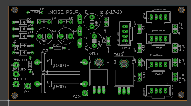
Here's the psup, based on the usual PAIA linear design you find in fracs.


PSUP was quickly off to china for PCB fab; back, built.

The first Psup built kept blowing up (I mean BANG!!! and smoke, total destruction) the diodes used for rectification. I pretty much sucked every part off the board looking for the short but never found it, so I  built another. Of course: Second one, almost all the same parts, same everything, worked.

Wow--That Diode Blew up Real Good!


Why did the 2nd one work? No, not the missing reg. It was something else.


OK with the power supply temporarily not exploding, I next found that all the stacks combined drew about 150mA on the + rail and about 30mA on the - side. There were at least 2 instances of the + rail being dropped to 8V or 5V for the Arduinos. This meant that the 7815 regulator I was using got very, very hot, even with a decent sized heatsink attached. 

I didn't want the damn lunchbox thing to melt, so, what to do?  

At digikey I found this part:


I figure this part was designed for engineering amateurs and general bozos like me, who design linear power supplies and ignore any sort of heat loading. Very nice!

It's almost a magic part: a switching regulator that's a direct drop in for a linear regulator--with 92% efficiency, something like that? so no heat! and after putting that in (it was a direct replacement size wise for the 7815) the heat problem was gone.  

New problem though--powering everything on, the + rail would sometimes refuse to come online. After a few power ons and offs, it would come up. Strange!

Probably some filter cap issue downstream, but, whatever; I never figured this out, but just flicking the master power switch off and on a few times before using the lunchbox in the studio didn't seem like a big deal; I thought of it as an old motorcycle that doesn't always start the first time, right?

Last thing to build was a "jacks board" to hold things like the power switches, power rail LEDS and so on--since I had some space I threw a 555 VCO on there, but it could have been anything, here it is waiting to be mounted to the power supply.

"Every Project needs a 555"


I then got out the Antique rocket ship/jr. scifi lunchbox I bought on Ebay a few months ago--perfect graphics and patina for a Lunetta synth right?

OK, I dropped in all the boards etc. Good news: The 3D printing came out OK, it provided a tight enough fit that I didn't need to cut up the lunchbox to screw anything in, it's all just a press fit in there, and so far seems to be good enough.


Last thing to do is get it in the studio and make sure it all works. It does! Joy! No smoke!  No Fire! Bizarre sounds!

The synth is odd craziness as you suspect, but overall I think it's mostly good for atonal beep-beep-beep non repeating sort of stuff. Think of an alarm clock you seriously want to throw off a cliff? 

On the demo it's about 80% audio out from the lunchbox, but I also have the lunchbox providing chaotic CV to things like a Rings module. Like the original NOISE! it seems good for both audio and CV.

As far as posting allo the schemos etc etc--well, there is a ton of PDFs, eagle files etc etc., I will just make a giant ZIP of all of it and post it soon. UPDATE: 8-22-20. Eagle files and other "as built" docs are now posted.  Go to my website here. I will try to add scan and add PDFs down the road.

Many thanks and big shout out to Martijn Verhallen of reverselandfill--thanks for the support and encouragement.

Wow--can't believe it's done.  

Enuf! There are bad fires right now in not so sunny California, so there are even more fumes to not breathe--don't breathe 'em. Hold your breath. 

Friday, August 14, 2020

LFO from 2003: Repair--Is Electronics Stupidity a Competitive Advantage?

 Let's get in the time machine and go back to the bad old days. I was just getting into AudioDIwhY. And I knew even less about audio electronic design and fab then than I do now.  

But out of the early days of my AudioDIWHY quest came a few modules I still use today and like a lot--one which is an LFO I conjured up from different dribs and drabs I found on the web circa 2003:


spiffy new front panel from FPE.....


As with a lot of my remaining 2003-2005 era modules: in August 2020 this one was showing its age; the original front panel had faded and was hard to read, and one of the switches had become sticky. It was built (poorly!) on perf. But I still liked the way it LFO'd and was using it all the time. It was time for a 20,000 mile tune up......


Yo! hand cut and drilled out of sheet aluminum; the legends are water slide decals.
 

I used Front Panel Express for a new front panel; easy! For the screwy switch I took a photo so as to replace it w/ correct wiring but after that the LFO didn't work; very nice.


Whatever....I went to my cache of documents to find the schematic for this puppy and guess what--NO SCHEMATIC FOR THIS LFO. Very nice!  

I think I remember how I built this: I found fragments of various LFO circuits on line, combined them into something that seemed at the time to make sense, and then tweaked components and values on the bench until I came up with something I liked. 

Who needs a schematic?

It's helpful when the gizmo doesn't work! To fix the circuit, I had to reverse engineer the mofo; tricky because the wiring and layout on the perf was full spaghetti western.

Still not sure I got the drawing 100% right? 


OK, some of that makes sense but some of it is--strange. Why use trimmers for TM1 and 2? Why use a 5K trimmer for TM3?  At the very least, now I'd put 50K in for TM3, which won't change things, but save a bit of stress on power supply for this circuit. But at this point I am not messing w/ any of it.  I might fab up a PCB based on the schematic above someday to see how and if it works. UPDATE 11-15-20! Yes, I did this, read on....

PCB based on reverse engineered schematic you see above. Works--sort of??

PCB of the LFO prime laid out, fabbed, and stuffed--and yep, mistakes abound.  First up, based on the original schematic you can find all over the internet (e.g. here, see fig 15), the op amp stage that produces the square wave has its inverting and non inverting terminals flipped.  How many times will I make this same mistake? Surprisingly the circuit still works, sort of, but the square wave looks crappy on a scope--a sort of square/triangle mix, and the triangle isn't very crisp. VERY NICE. Still musically useful? Maybe. Next, the voltage feeding TM3 should be V-, since it's inverting; as it is, you can only bias the waveform down, between GND and V-, which isn't what I want. Finally the frequency knob is wired backwards, so CCW is as fast as it will go. These are all easily corrected, but, yep, based on the 3340 kludge rule, I'll have to fab another one....

As long as the LFO was on the lift: The module also had a power cable that was too short, I remember making this by hand out of crimping tools. 

 
I replaced that with what I've been using for the past few years: expando and a factory 4 conductor, PAIA Frac-friendly power cable, much fancier and less likely to get tangled:


But some of the crap-stuff was left in there: The grounds for the output jacks are 3x bare wire. Why? No idea. I guess I mostly just didn't know what I was doing.


If you've made it this far, no doubt you are wondering: why am I even writing about this? To a large degree this week's work was a simple repair and front panel replacement, and isn't noteworthy.  

Besides, we hopefully all get "better" as we do pursue a hobby more and more so yes, I can go back to earlier work and think--wow, that design choice was really stoopid!

Instead, what I've been mulling over: back in 2003, since I had no idea what I was doing at all, I sat at the bench and screwed around with perf, plugged in components and listened, plugged in another part and listened, went back and swapped in B for A, and on and on. Some of the component choices I ended up with still baffle me, but, whatever. What I got back in the hit-r-miss days was almost always something I really liked, and this LFO is one of those. To wit: The BIAS offset values are, to my ears, exactly where they should be, the frequency control range is as well. Sure, this LFO is only triangle and square, but fine, that's what I need 90% of the time. 

If I designed an LFO now I'd add all sorts of other goodies--variable waveforms, LEDs, CV control of frequency, blah blah and yet I'd wager this LFO is still where I'd go when I needed some quick LFO. 

So the lesson here, I think, is that the days of just goofing around, getting stupid, cobble and mod, and not worrying about "getting it right" should continue--always. To put it another way: getting it right in terms of sound is more important than getting it right and should never be overlooked.  

Update: reverse engineering my own design is done.  Post about working circuit is here.  Post about the Eurorack version of this circuit is here

Monday, August 10, 2020

Noob 3D Printing--Monoprice Voxel 3D setup--For an Electronics Lab? But (audioDI) WHY, Voxel, WHY?

Hello again. I love Youtuber/DIY dude Andreas Speiss--perhaps not enough to propose, but still, I am very fond of him, and try to watch all his videos.  

Blame Andreas on this post--because this diWHY quest starts entirely with the video here. Go to about 1:02....In my lab I had all the essential tools mentioned but not a 3D printer. I fully agree with all of A.S.'s other essential tools, so why don't I have a 3D printer?  Um....Because I couldn't really see what I'd use one for.  

But then Covid hits, I am bored, and have some time to learn new things. My trip to Spain is cancelled, that money is in my pocket, so I figure why not buy a 3D printer, learn how to use it, and decide what to use it for later.

Lots of research followed and the printer that, as of writing this post, gets the nod as "best for 3D printing newbies" is this one:"Monoprice Voxel 3D:"

But is the Voxel really called a IIIP? Is IIIP anywhere in literature, the web, etc?  Can you search for IIIP and learn about it? Uh--no!


SOLD! I paid about $420USD for this, delivered, not super cheap, but from the endless reviews it's a good spend: this printer has a lot of time- and sanity-saving features, many only available on printers that cost a lot more: touch screen, self leveling ability, Ethernet and WiFi,  you get the fresh idear.

It also has a reputation for the default settings producing useful output--and not a puddle of goo. Good.


The printer showed up quick, and then, getting it set up was easy; there was a lot more packing material to remove than the quick setup guide showed, but, that's OK. Using the same quick start guide, it was easy to load up PLA filament, heat up the nozzle, and print out the sample cube--which came preloaded in the printer's memory--call up this test object using the touch screen panel and tell it to print.

Righto.....and here is what I got first time around for my cube:


(Not a cube....) 

Rats! This is supposed to be the easiest, most idiot-proof 3D printer around and I can't even print a cube. What now?  I figured I'd better read the manual, since the quick start guide might be a bit too quick.  

The manual can be downloaded here, and says I needed to calibrate the print nozzle first before printing (not mentioned in the quick guide!)  Did that and I ended up getting what is below, on the right:


Success! I joyfully emailed this pix to my family as well as my psychiatrist girlfriend, who seemed happy for my victory but puzzled and maybe even a bit concerned.

OK now that I can print the sample it's time to draw up something right? What 3D CAD software to use? I have messed around with extruding things using Photoshop, but not real 3D CAD. There are many choices for this--and I had to learn one. Tinkercad is popular--but since I have long owned Eagle CAD, I get a free license for Fusion 360, which seemed like a heck of a deal. (Whack! Take that, all you guys at the geek meetups telling me to switch to Kicad! )

I downloaded Fusion 360 months ago and started to mess with it but it made zero sense. Maybe time to try again? 

As always--YouTube to the rescue. I found a most-excellent tutorial here.  Parts I II and III took me through the basics, and after I was done with the 3 vids I could conjure up simple shapes and get them realized in 3D:  


Time to print: Turns out you need a "slicer" to turn the 3D output (".stl") into a digital format almost all 3D printers eat ("gcode").  The program almost everyone uses for doing this conversion--it's free--is called CURA. I downloaded that and turned the stl into gcode and guess what? The Voxel didn't accept the gcode file I presented to it!

Went through the manual again--nothing. Why won't gcode--or even stl, which supposedly the printer can read--work? 

I went through a bunch of reddit forums and other stuff--nothing.   

I finally found the answer in the video here: The Monoprice Voxel 3D doesn't use gcode, it uses something else; so to make the voxel work you have to use the FlashPrint slicer on the Monoprice website (here--go to the bottom of the page--very bottom--the section that says "Support Files").

Furthermore, Cura has no way I could find to talk to the Voxel 3D printer using Ethernet--i.e., there are no details about a "print" command from the Cura slicer--but the Voxel FlashPrint slicer does, which solves another poorly documented and critical issue: how I send 3D jobs to the printer using Ethernet.

Indeed, I stumbled around and cursed a lot on this Cura vs. Flashprint issue. 

But, once I found the right slicing software, and got it going on my PC, things got very easy. 

Now it's print time. So--Um--really! What am I going to make? Guess it's time to figure that out.

Motorizing the pursuit: If you've been following this blog, I have been working for over a year on a Lunetta synth based on Reverselandfill's most excellent Noise! chaotic oscillator.  I have gone winchester mystery house, coming up with a bunch of boards to modify the lunetta madness. Posts about the Noise! build are here , here, and here (as well as here ). Will it ever get finished? Who knows?

Update 6-1-24. By default FlashPrint jobs produce a "raft", a bed of sorts, that the print job sits on. This helps the part adhere to the base but sometimes I don't want this; to get rid of it, right before printing there is an option "Include raft"?  Say "disable".

It's time to put all 8 PCBs into a case, so why not 3D up some feet for the project's PCB "stacks"? Here we go:


INDEED. I used 5 minute epoxy to glue the 4-40 nuts into the feet. I could have designed 4-40 threads the CAD  design but I didn't know how strong or brittle that would be, and it's good to know that epoxy, metal, and PLA like one another--1001 uses.


Yep, screws right on. Seems to work! Victory!

Onward! I have decided that perhaps I love 3D printing.....like the Teensy Audio, this acquition will change how I do DIwhY and the (extremely underground) hits keep coming.

Moving on--time to finish the Noise! synth. Next week I hope? Maybe, maybe not.

Time to wrap it up: 3D printing outgasses are supposedly toxic, hopefully less than covid-19. so as always don't breathe the fumes, but really, you should check out the Voxel if you're thinking of getting into 3D printing--wow, what a gizmo.


JTAG to SWD Converter

Readers: If you'd like to build the project featured in today's post, please go to PCBWAY's Community pages--gerber file, KiCAD ...