Saturday, June 21, 2025

"LFO MINI": Small and Simple CA3080 modulation source

Readers: If you'd like to build the project featured in today's post, please go to PCBWAY's Community pages--gerber file; KiCAD 9 project/pcb/schematic/library files, a couple of B.O.M.'s, and more, are here.  

You can also help out this site immensely by checking out PCBWAY using the link here. Thanks!

============

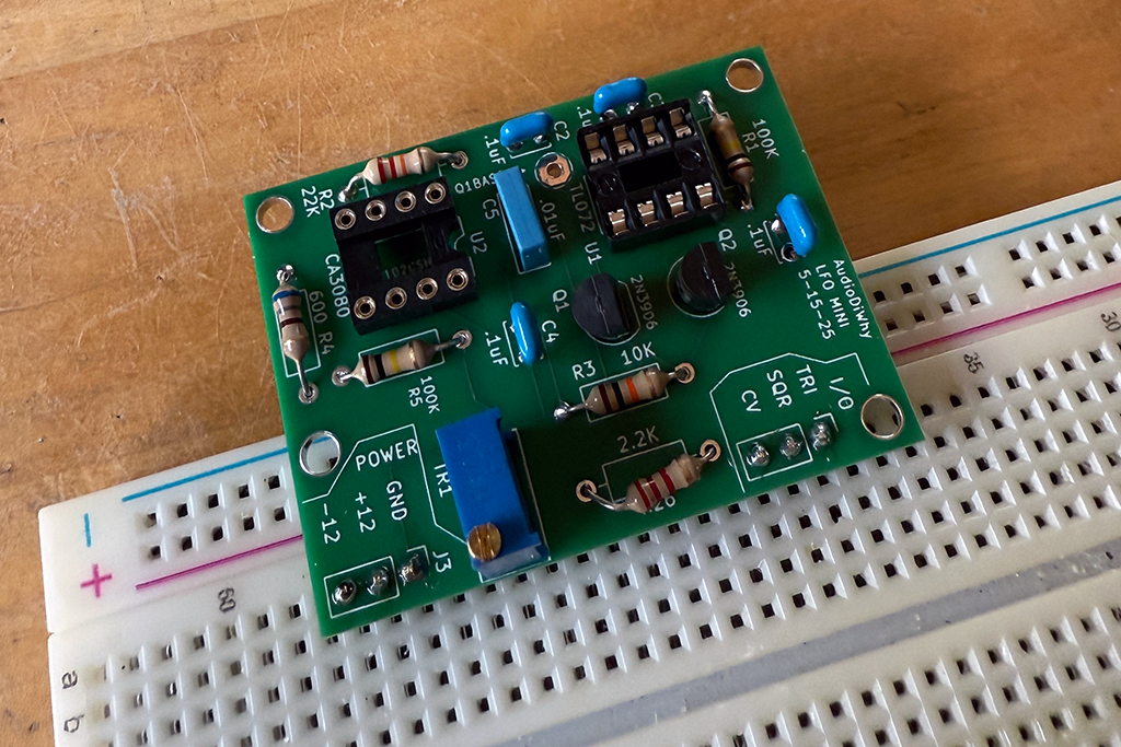
Carrying on with the latest "keep it simple" and "just say no to AI" posts: this time I designed, laid out and populated a small CA3080 based LFO PCB. Works!


 The basic OTA > op amp core was stolen from EFM's LFO2; see the previous post here; an online simulation of the current source for the 3080's "Iabc" pin 5 is here.


Laying this out was easy, but I had to make a few decisions that seemed a bit arbitrary:

  • I used Through Hole Technology not SMD. I don't do a lot of through hole work any longer, but have so many THT parts lying around, I felt like I had to use them?
  • I had a tube of NOS CA3080's so I used a few. If you build this LFO you'll need to find this IC. The DIP version of this IC is no longer made, but, as I am writing this post I see plenty for sale on Ebay, Amazon and elsewhere--it's not unobtanium, at least not yet.
  • Inputs rails were +/- 12V, but the circuit should work fine with anything from maybe +/- 15V to +/- 9V.
  • Inputs and outputs were put on 3 pin 100mil headers.

One modulation input was current limited by R5 and brought out to the "CV I/O" pin, but additional modulation sources could be easily added--wire up 100K resistor(s) between your CVs and the "Q1BASE" wirepad:

Be careful! If you leave off the 100K resistors and plug your additional CV directly into the "Q1base" wirepad you risk blowing up transistor Q1. Make sure to current limit the additional CV with a series resistor as shown.

From here this was an easy build:

I got 10 LFO minis from this blog's loyal Sponsor, PCBWAY, for $5USB (excluding tariff and import fees).  You can greatly help this blog by checking 'em out here.


Testing....

The LFO worked first time--almost.

I had a short between two of the bypass cap pins (C1) initially and the CA3080 got hot; once I cleaned up the sloppy solder everything was fine. Fortunately I didn't smoke the CA3080.

Using only the 10K trimmer board for modulation the LFO goes from < 1hz well into audio range. To calibrate, with no CV at input, I hooked the square wave output to my scope and turned the trimmer until the frequency started to change (it took several turns, and I thought maybe the circuit didn't work, but it did--I had to keep turning). I ended up settling in at about 200hz without any CV.

Then, with +/- 12V CV added, I got a wide range of frequencies, from reeallly slllowww to well up into the audio range--this is a the hallmark EFM design: cool and simple.


Output for triangle is about 6V P/P, for the square it's close to the rails. Since I designed the LFO-MINI to be a daughterboard, I figure whatever I plugged it into could gain up or down these output amplitudes, so for now this was good enough.

What's next? It would be easy to make this a dual super-small LFO using SMD parts and an LM13700. 

Overall, this will find its way into some "quad mod" type modules swirling around in my head, that combine random voltage sources, audio inputs, a couple of these LFO's, and who know what else. 

Until then, don't breathe the fumes.

Saturday, June 7, 2025

BNC to 3.5mm Adapter Board--Sans AI

Readers: If you'd like to build the project featured in today's post, please go to PCBWAY's Community pages--gerber file; KiCAD 9 project/pcb/schematic/library files, a B.O.M., and more are here.  

You can also help out this site immensely by checking out PCBWAY using the link here. Thanks!

============

At my day job I'm up to my knees in Artificial Intelligence. Thank goodness I can do something simple and stupid for AudioDiWHY and get away from AI for a bit.

How about a 3x BNC to mono 3.5" adapter PCB? BNC's can be found on most of my bench test gear, and 3.5" jacks are common to a lot of audio synthesizer gear as well as most things DiWHY.  

Sure, I could buy or make BNC to 3.5mm mono adapters/adapter cables, but what fun is that?

THE BOARD

In addition to the 3x breakout the PCB has signal and ground brought to wirepads.

For the audio jacks I used my favorite horizontal 3.5" switching mono jack, the Switchcraft 35RAPCVAV

KICAD 9 doesn't provide a footprint for this connector, so I made my own. Get it from Github, here (a library with all my custom KICAD footprints is here).

For the BNC's I had a lot of choices, but, in the spirit of this blog, I chose cheap Chinese BNC's sourced from Amazon: "Superbat":


I had to make a custom a Kicad footprint for this component as well, get it here.....and, assuming the link still works--you can buy the connectors here.  

THIS BLOG'S SPONSOR


Once again helping with my DiWHY addiction is this blog's humble sponsor, PCBWAY.  They do all sorts of great fabrication, CNC/3D printing, assembly, and much more.

Please help out this blog and check them out--use the link here.   

DESIGN AND BUILD

Designing the PCB was easy. I used Kicad 9 and made the board less than 100x100 mm to lock in PCBWAY's ridiculously low price of $5USD for 10 boards.


Happiness is new boards from PCBWAY!


SE HABLA TARIFFS?

For the first time I had to pay a tariff for these PCB's. It was surprisingly tricky to figure out how to do that.

Here is the process (for DHL Express; other shippers will differ):

  • Print DHL's POA form (download it here). As of 6-8-25: You have to complete this form, and have DHL sign off, to get shipments from China to the U.S.A. using DHL.
  • Go to page 2 and figure out who/what you are. 
  • I am an "individual" so I had to fill out the boxes listed in that form on pages 3 and 4. Yes, I had to provide my social security number.
  • Sign the form.
  • Scan the completed form and email it to DHLExpressUSA.POA@dhl.com 
  • They emailed me back quickly--one business day--to acknowledge they got the form and it was OK.
  • After my order shipped from PCBWAY, DHL sent me an email telling me how much additional USD I had to pay them before I could take delivery of the goods.  
  • For me, it was about half the cost of the boards and another $18 USD for handling fees.
  • Yes, this raised the price of the boards, but they were still a lot less expensive than any PCB fabrication houses I could find in the US, even with the tariff in place.

With that out of the way, I got building!

USELESS BUILD PHOTOS


The BNC's are pretty chunky; I had to increase my solder temp to about 750 degrees F to get their leads hot enough to fuse with the solder.

It was hard getting the BNC's perfectly aligned but everything works--good enough.

USE CASE?

If I ever get time I will use this adapter board next time I fire up my QuantAsylum Audio QA403 test rig; right now, with all the adapters and jumper cables needed to hook A to B and B to C and C to D my bench quickly becomes covered in  spaghetti. Hopefully this simple BNC to 3.5mm adapter board helps sort this a bit.

I also might build a few of these to make the BNC's behind my test gear--like the trigger input to my Siglent SDG1025--easier to patch.


Beyond that? Who knows. Adapter board DiWHY can be mindless fun and soldering connectors on a simple PCB is satisfying. 

Analog Devices ADG413--Incredible Audio Switch IC

Two of my favorite social media (S&M) things:  IMSAI Guy's   Chip of the Day vlog and finding a great surplus electronics deal on th...